Gun sight using LED illumination

a technology of led illumination and gun sight, applied in the field of devices, can solve the problems of increased difficulty in low or variable lighting conditions, reduced light output, and reduced illumination efficiency,

Active Publication Date: 2016-03-31
GWILLIM JR REESE C
View PDF0 Cites 18 Cited by
  • Summary
  • Abstract
  • Description
  • Claims
  • Application Information

AI Technical Summary

Benefits of technology

[0018]The above gun sight system makes apparent a related method for modification of a gun sight system to add illuminated sights. The stock sights are removed, which may require a professional gun smith. However the installation of the new sights may be done by the gun owner. A substrate is secured (e.g. by adhesive) to the slide of a handgun. The front and rear sections of this substrate adhere to the top of the slide, while a contiguous, perpendicular bridge adheres to the side of the gun slide. A front and rear sight (e.g. LED illuminated sights) are secured onto the slide via the substrate. A window in the sights allow illumination from the LEDs to be seen by the user during low light conditions. In one embodiment, the LEDs are of different colors.

Problems solved by technology

Given that a handgun may be used in a life threatening situations, the weapon's user has very little time to aim the weapon at a target.
Additional difficulty is encountered in low or variable lighting conditions when the front and rear sights are more difficult to see.
There are a number of known drawbacks to the use of tritium or other radioactive gasses in this application of use in a gun sight.
In addition, the phosphorescent coating also may be subject to degradation over time, could be subject to photo bleaching, or other factors which degrade its efficacy.
It is difficult to tell the age of the tritium, and used guns or older sights are difficult to evaluate.
A user is faced with a continually degrading light source, which is not ideal.
The average shooter or consumer can't easily or carefully take off stock sights (or what are called “iron sights”) alone.
However this is not an easy process and requires some skill to avoid damaging the firearm or the sight.

Method used


Image

  • Gun sight using LED illumination
  • Gun sight using LED illumination
  • Gun sight using LED illumination

Examples


Embodiment Construction

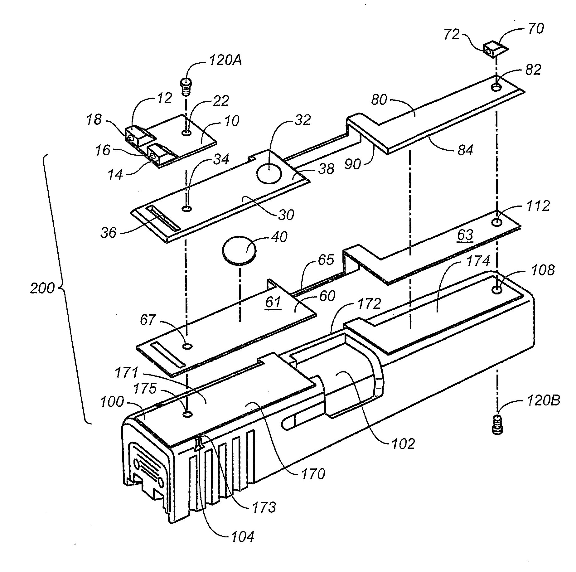
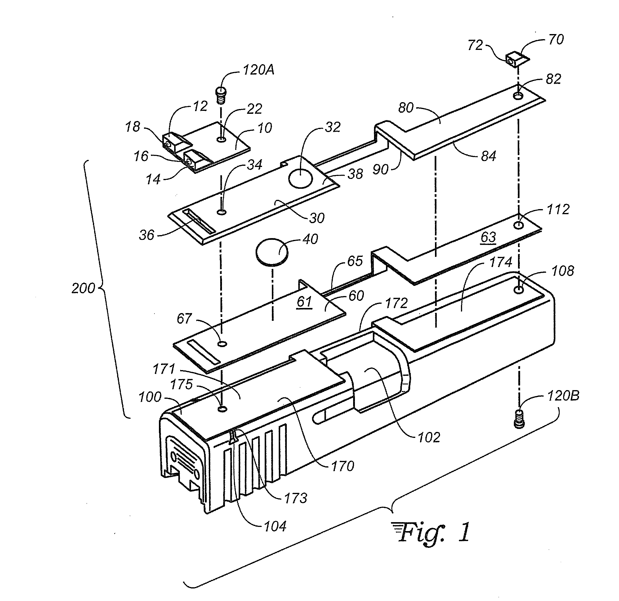
[0028]With reference to FIG. 1, an exploded view of an embodiment of the invention shows a gun slide 100. This slide is the type that may be used on a Glock® brand automatic handgun. The slide includes a central opening 102 through which shell casings are ejected after firing. A dove tail mounting slot 104 allows mounting of the stock rear sight. The stock front sight is attached using a screw 120B, through front sight mounting hole 108.

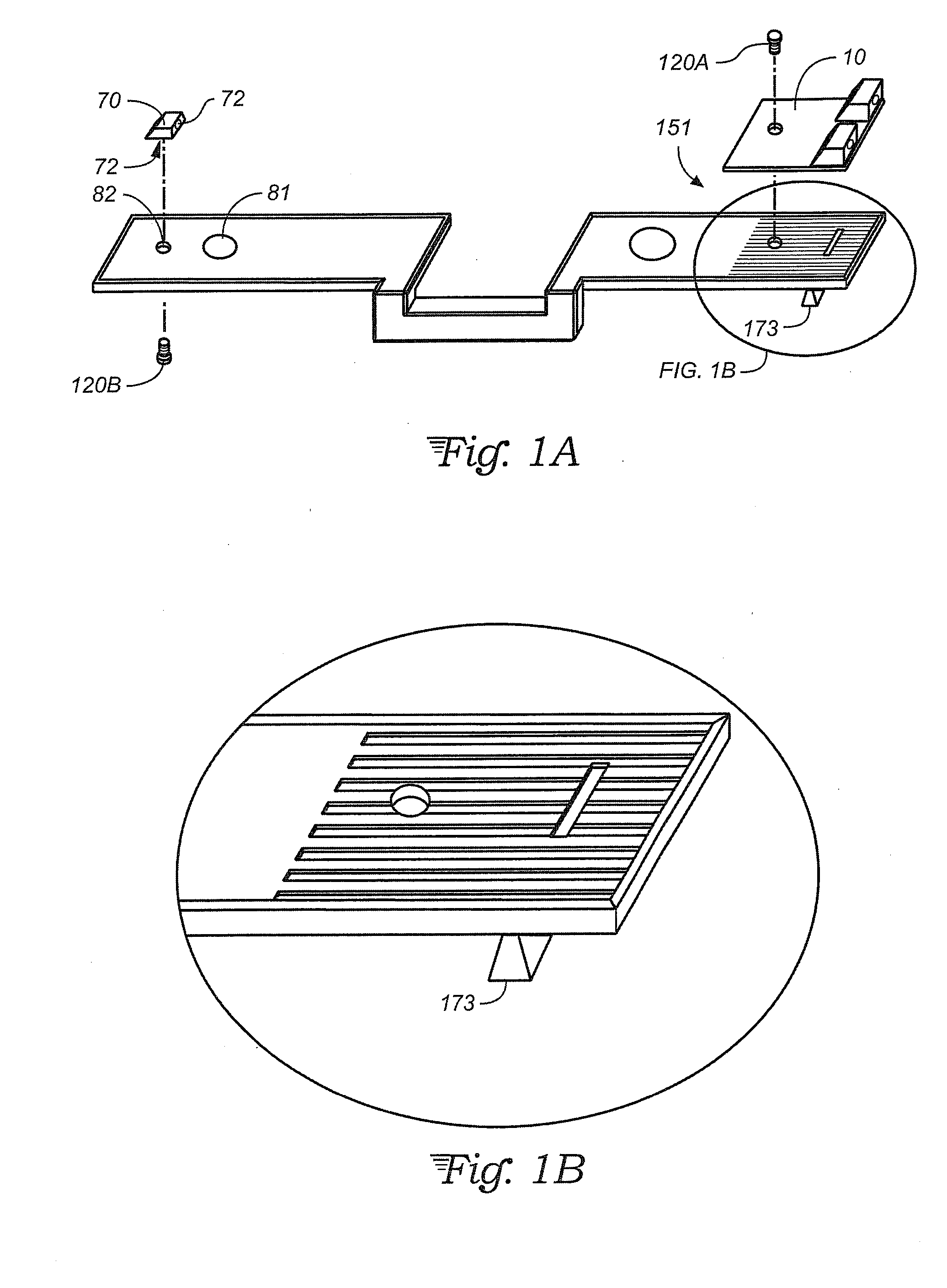
[0029]The illustrated embodiment includes a bottom housing 170 and a top housing 30 which are joined together to encase a printed circuit board 60. A detail view of the printed circuit board is shown at FIG. 1C. The bottom housing 170 and top housing 30 may be made of high impact plastic. Bottom housing 170 has a underside adhesive 176. This may be an adhesive that includes a release liner adhering to the adhesive layer. The release liner could be removed and the device mounted on a gun. The adhesive would then cure, providing a firm attachment to th...


PUM

PropertyMeasurementUnit
distanceaaaaaaaaaa
angleaaaaaaaaaa
shapeaaaaaaaaaa

Abstract

A gun sight system including a housing, comprised of a top housing layer and a bottom housing layer. The housing includes a front end and a rear end configured to adhere to the front and rear of the top surface of a gun slide. A central portion of the housing is configured to be perpendicular to the front top and rear top sections. Within the housing is a front and rear circuit board, including at least one battery mount, at least one switch, and a front LED and a rear LED. The housing has a window to allow light from the LED to shine into a window on a front and rear gun sight. A light pipe within each gun sight allows the light to be seen by the gun's user.

Description

TECHNICAL FIELD[0001]The present invention relates to devices to be used on a firearm and more specifically to a device providing an illuminated gun sight to allow use of the sight during low or variable lighting conditions.BACKGROUND ART[0002]Gun sights are used on firearms to aid in aiming the firearm. Properly trained gun owners (including military and law enforcement) will use the sights to aim the weapon. Given that a handgun may be used in a life threatening situations, the weapon's user has very little time to aim the weapon at a target. However proper aim is critical to minimize potential injury to bystanders and to ensure that the target threat is neutralized.[0003]A standard handgun sight includes a single, raised front sight centered at the top, front surface of the gun barrel or gun slide. The front sight is a single raised projection. The rear sight is an elongate projection with a central notch at the rear of the gun. The central notch of the rear sight is centered on ...

Claims


Application Information

Patent Timeline
Patent Type & Authority Applications(United States)
IPC IPC(8): F41G1/34
CPCF41G1/345
Inventor GWILLIM, JR., REESE, C.
Owner GWILLIM JR REESE C
Why Eureka
Try Eureka