Hammermill hammer with pin-hole insert

Inactive Publication Date: 2009-10-08
RIVERSIDE CO LLC
View PDF4 Cites 16 Cited by
  • Summary
  • Abstract
  • Description
  • Claims
  • Application Information

AI Technical Summary

Benefits of technology

[0008]A method for prolonging the life of a hammer in a hammermill is also contemplated by the present invention. The method includes the steps of: mounting a hammer in a first position on a rotor of a hammermill, wherein the hammer includes at least one impact end and a body, an elongated pin hole in the body, a longitudinal mating feature disposed within the elongated pin hole, and an insert ha

Problems solved by technology

The hammers are subjected to extreme wear conditions, and must often be replaced at significant cost.
As the hammer is in use, the tip is subjected to the most wear.
This practice prolongs the life of the hammer, but movement of the hammer pins from one pin hole to another is still costly and inefficient.
Although existing methods for extending the life of the hammers have certain benefits and advantages, existing methods also have

Method used


Image

  • Hammermill hammer with pin-hole insert
  • Hammermill hammer with pin-hole insert
  • Hammermill hammer with pin-hole insert

Examples


Example

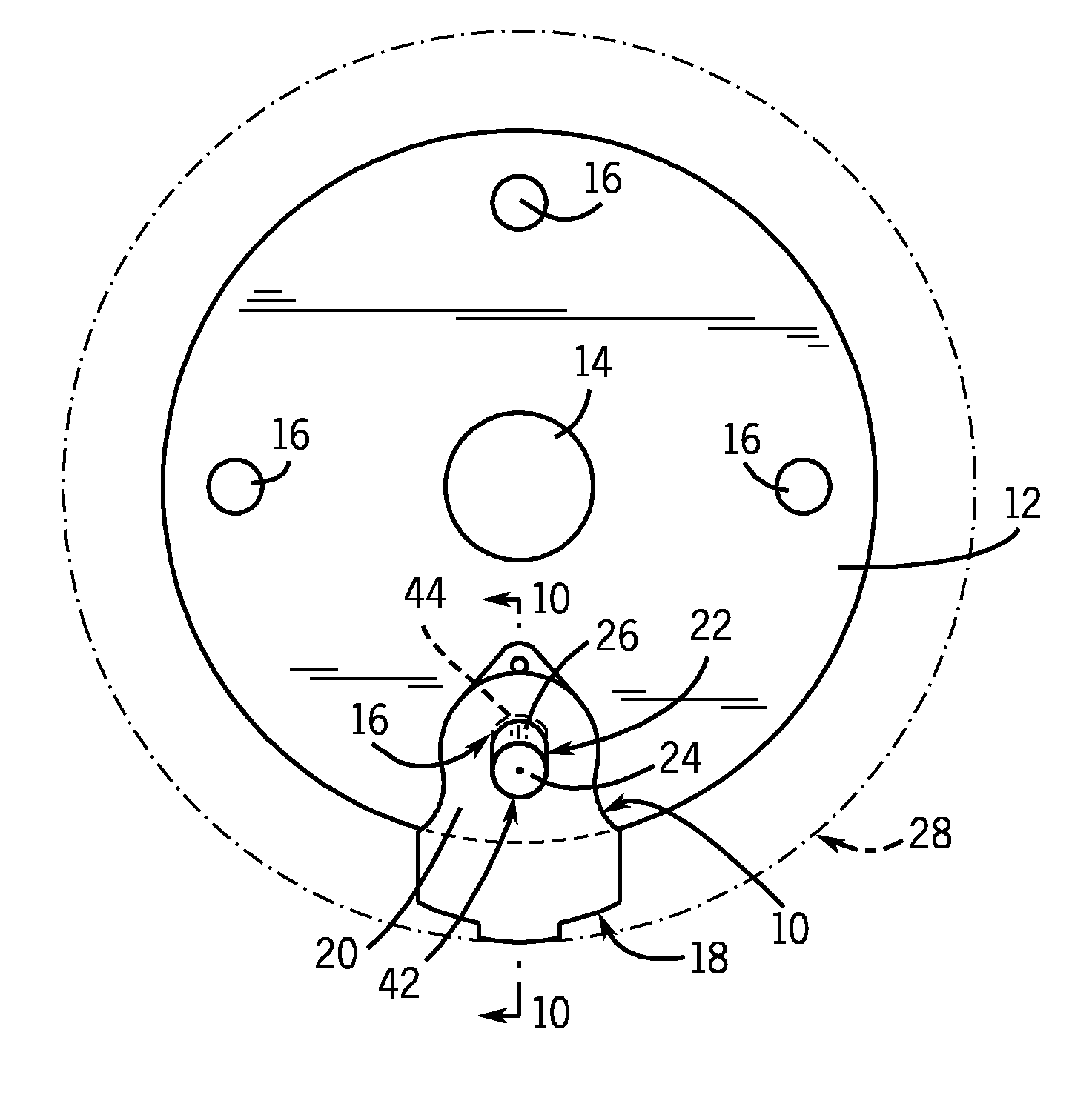
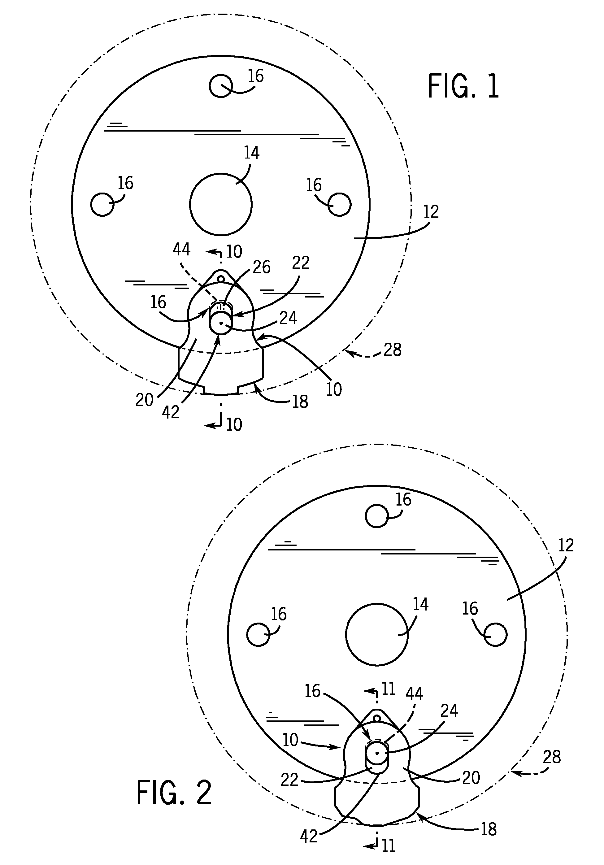
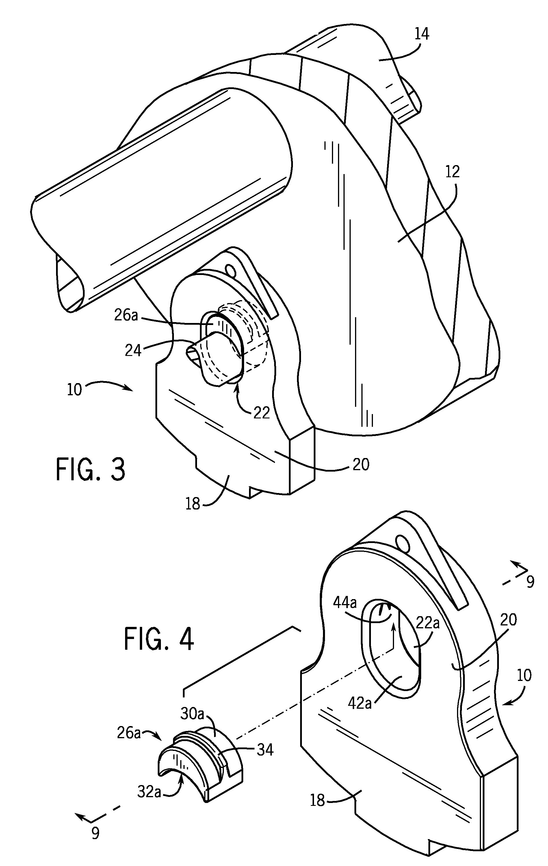
[0029]The present invention is a hammer with a pin-hole insert for use in hammermills. Referring now to the drawings, FIG. 1 shows a hammer 10 according to the present invention mounted in a first position on a rotor 12 and shaft 14 of a hammermill. The rotor has four pin holes 16 for mounting hammers thereto, but only one hammer 10 is shown for purposes of illustration. Other numbers of pin holes 16 and hammers 10 could be used. A disc rotor is shown, but other types of rotors could also be used such as radial or spider rotors. The hammer 10 includes an impact end 18 and a body 20. Other hammer types could also be used, such as those having multiple and / or opposing impact ends, some of which are known as bell-type and bow tie-type hammers. The body 20 of the hammer 10 shown includes an elongated pin hole 22 for receiving a pin 24 for mounting the hammer 10 to the rotor 12. The elongated pin hole 22 has a first end 42 and a second end 44. In FIG. 1, a pin-hole insert 26 is disposed ...


PUM

PropertyMeasurementUnit
Shapeaaaaaaaaaa

Abstract

A hammer for a hammermill includes an elongated pin hole and a pin-hole insert that allows the hammer to be mounted in a first position and a second position on a rotor of a hammermill to prolong the useful life of the hammer. The insert is installed in the pin hole using corresponding mating features. A hammer assembly and method for prolonging the life of hammers in a hammermill are also described.

Description

FIELD OF THE INVENTION[0001]The present invention relates generally to hammermills for shredding scrap materials, and more particularly to a hammermill hammer having a pin-hole insert for adjustable installation.BACKGROUND OF THE INVENTION[0002]Hammermills for shredding scrap materials such as automobiles shred or fragment the scrap materials using a rotor assembly with a plurality of impact hammers mounted thereon. The hammers are generally mounted to the rotors using pins and swing freely on the pins as the rotor rotates and the hammers contact scrap materials. The hammers are subjected to extreme wear conditions, and must often be replaced at significant cost. Many replacement methods and hammer designs have been employed in an effort to reduce the frequency at which the hammers must be replaced and the cost to do so.[0003]One common practice for prolonging the life of the hammers is the use of two-piece hammers or hammers with replaceable tips. As shown, for example, in U.S. Pat...

Claims


Application Information

Patent Timeline
IPC IPC(8): B02C13/00B23K31/00
CPCB02C2013/2808B02C13/28
Inventor STELK, JOHN C.
Owner RIVERSIDE CO LLC
Why Eureka
Try Eureka