

Heating Assembly for a Vapour Generating Device
- Summary
- Abstract
- Description
- Claims
- Application Information
AI Technical Summary
Benefits of technology
Problems solved by technology
Method used
Image

Examples
Embodiment Construction
[0038]We now describe an example of a vapour generating device, including a description of a number of example heating assemblies and an example vapour generating substance.
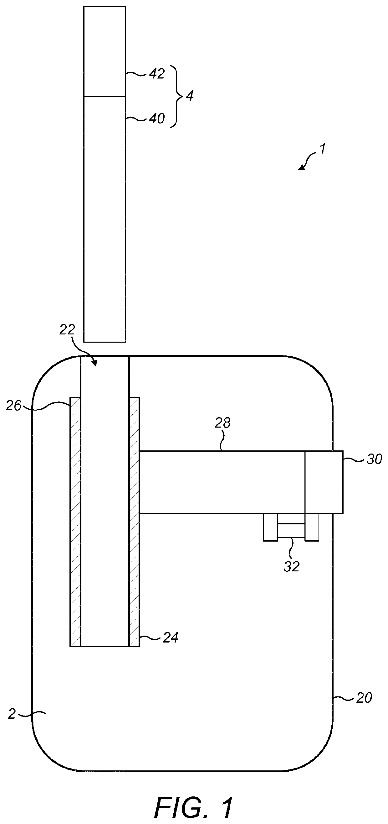
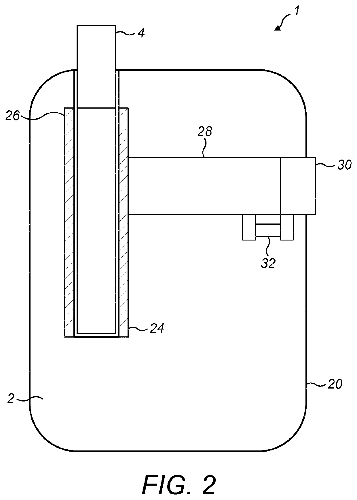
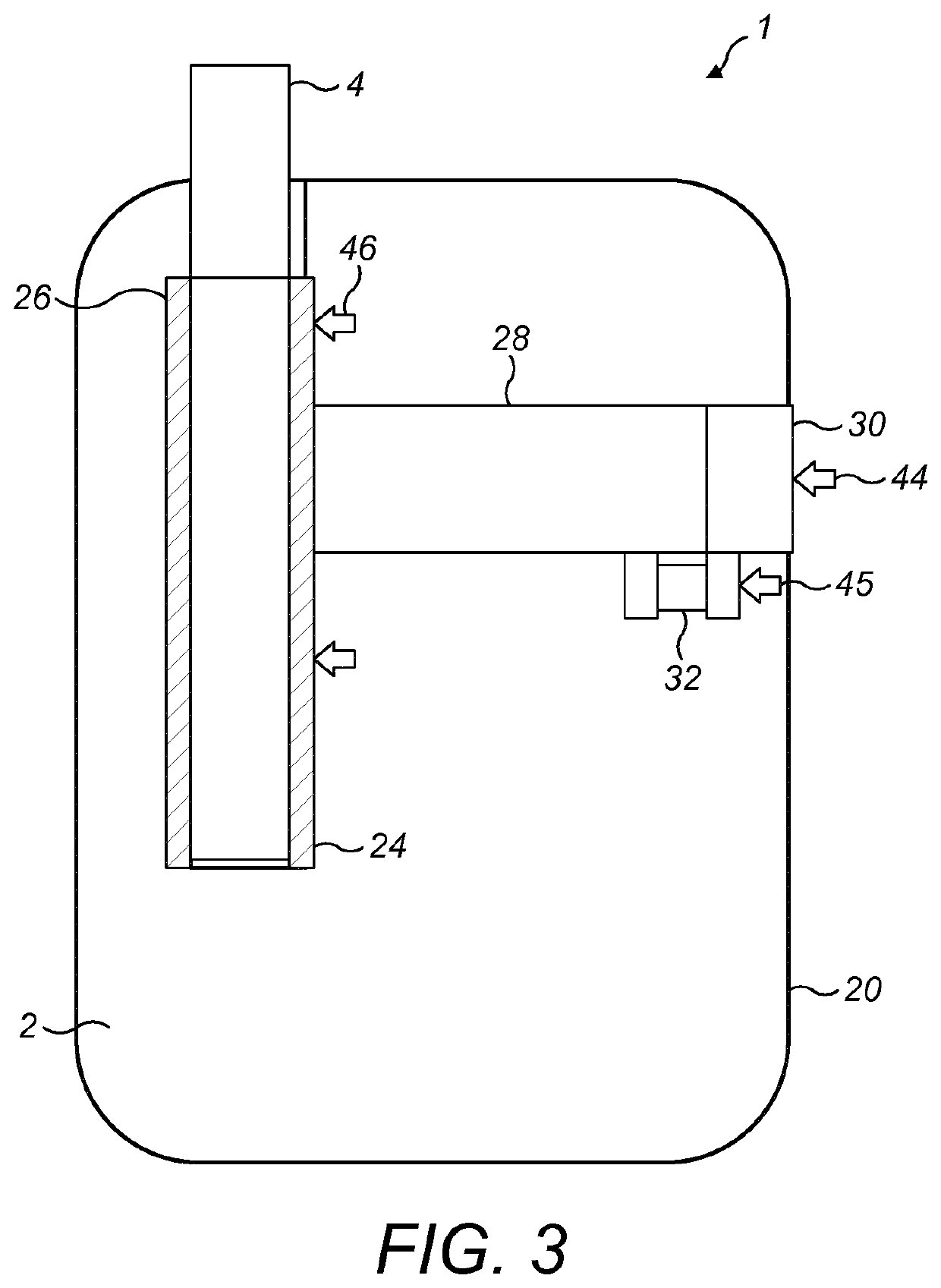
[0039]Referring now to FIG. 1, an example vapour generating device is generally illustrated at 1. The example vapour generating device is a hand held device (by which we intend to mean a device that a user is able to hold and support un-aided in a single hand).
[0040]The example vapour generating device 1 is shown in FIG. 1 in a disassembled arrangement. This shows two parts of the vapour generating device, namely a heating assembly 2 and a vapour generating substance 4 in a separated arrangement.
[0041]The example heating assembly 2 shown in FIG. 1 has a body 20. The body has a bore in one surface (the upper-most surface shown in FIG. 1). The walls of the bore form a heating compartment 22 and the top of the bore defining an opening in the upper-most surface of the body of the heating assembly. The heating compart...
PUM
 Abstract
Description
Claims
Application Information