Method and device for control of an auxiliary a motor vehicle

Inactive Publication Date: 2001-08-30
SCANIA CV AB
View PDF0 Cites 4 Cited by
  • Summary
  • Abstract
  • Description
  • Claims
  • Application Information

AI Technical Summary

Benefits of technology

0003] One purpose of the invention is to provide a method and a device of the type already described which, by simple means, ca

Problems solved by technology

In many cases, it is sufficient to operate the unit for a short period at regular intervals to condition these components, examples of which include seals and gaskets which must be exposed to fluids to prevent drying and ageing, non-friction bearings in which th

Method used


Image

  • Method and device for control of an auxiliary a motor vehicle

Examples


Example

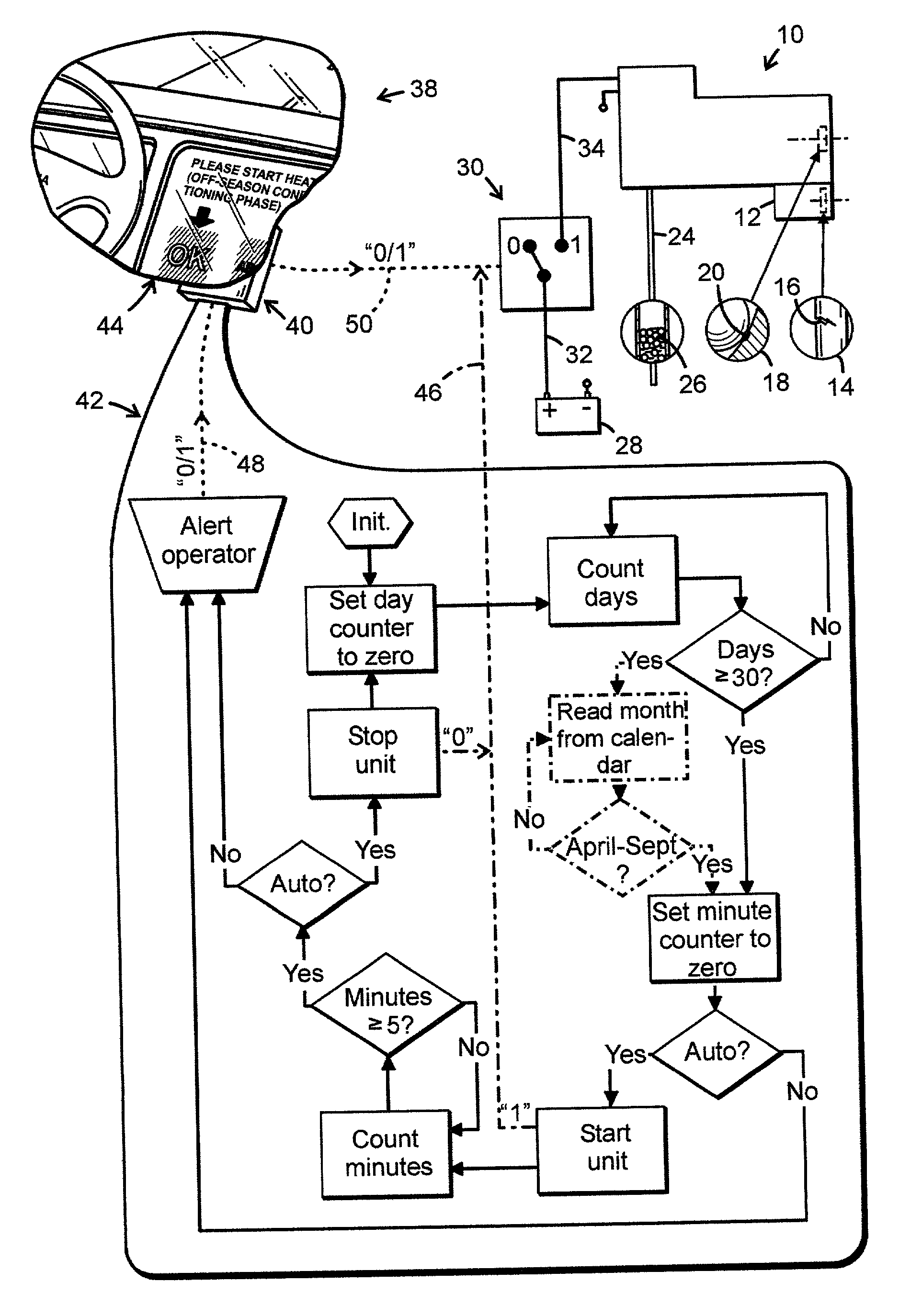
[0011] On the drawing, a mechanical auxiliary unit in the form of an auxiliary heater for a motor vehicle is designated generally 10. However, the auxiliary unit may also be an air conditioning unit (not shown). In the example shown, the heater is a water heater consisting of a burner and a water pump 12 for circulating, in a known but not illustrated manner, water heated by the burner.

[0012] As shown on the drawing, an auxiliary unit of this type normally contains the following components: a seal 14, a non-friction bearing 18 and a fluid line 24. As already stated, components of this type require to be operated for short periods at regular intervals to avoid impairment of the operation and life of the auxiliary unit 10. In more specific terms, the seal material 16 may dry out and crack, an area of static metallic contact 20 may be subject to fretting corrosion due to vibrations and the level of fluids, such as diesel oil, in a supply line may fall, forming an agglomererate 26 which...


PUM


Abstract

Method and device for controlling an auxiliary unit (10) in a motor vehicle by means of a device consisting of a control unit (40) and a switch (30) for switching the auxiliary unit on and off. To ensure the maintenance of an auxiliary unit of this type and to prolong its life using simple means, it is proposed, among other things, that the control unit (40) will repeatedly signal actions to be taken to a driver of the vehicle or directly to the switch. A first action is the switch-on of the switched-off auxiliary unit (10) at a specific point in time if it (the unit) has been switched off for a long period of at least some weeks. A second, succeeding action is the switch-off of the unit (10) switched on in the manner described, after a short period of at least some minutes.

Description

TECHNOLOGY[0001] The present invention relates to a method of controlling a mechanical auxiliary unit in a motor vehicle by means of a device consisting of a control unit and a switch for switching the unit on and off. The invention also relates to a device for implementing the said method.STATE OF THE ART[0002] Examples of mechanical auxiliary units of this nature include auxiliary heaters and air conditioning units. Units of this `seasonal` type are used intensively during winter or summer periods and, thereafter, remain basically unused until the next period of use. The use of components which require maintenance to ensure their life is also a common feature of such units. In many cases, it is sufficient to operate the unit for a short period at regular intervals to condition these components, examples of which include seals and gaskets which must be exposed to fluids to prevent drying and ageing, non-friction bearings in which the metallic and line contacts must be shifted when ...

Claims


Application Information

Patent Timeline
IPC IPC(8): B60R16/02B60H1/00B60H1/32B60K37/06B60L1/00F25B1/00
CPCB60H1/00735B60H1/00964Y10T307/766Y10T307/951
Inventor MELIN, SEVEN-ANDERSDANIELSSON, JAN
Owner SCANIA CV AB
Why Eureka
Try Eureka