Differential transmission line including two transmission lines parallel to each other

Active Publication Date: 2009-12-24
PANASONIC CORP
View PDF5 Cites 7 Cited by
  • Summary
  • Abstract
  • Description
  • Claims
  • Application Information

AI Technical Summary

Benefits of technology

[0031]According to the differential transmission line of the present invention, the slots are formed in the first grounding conductor so as to sterically intersect with the first and second signal conductors and to be substantially orthogonal to the longitudinal direction of the first and second signal conductors. Therefore, the unnecessary mode conversion that occurs due to a difference in the wiring length between the differential wiring lines generated at the bends and the like of the conventional differential transmission lin

Problems solved by technology

However, at the bends of the differential transmission line (i.e., bend regions of the two microstrip lines 20a and 20b), unnecessary mode conversion from the differential signal to the common-mode signal easily occurs.
Since the unnecessary mode conversion significantly occurs as the transmission frequency increases at the bends of the differential transmissi

Method used


Image

  • Differential transmission line including two transmission lines parallel to each other
  • Differential transmission line including two transmission lines parallel to each other
  • Differential transmission line including two transmission lines parallel to each other

Examples


Example

[0052]Preferred embodiments of the present invention will be described below with reference to the drawings. It is noted that like components are denoted by like reference numerals in the following preferred embodiments. Moreover, dashed lines show components in the hidden positions in the drawings.

Preferred Embodiments

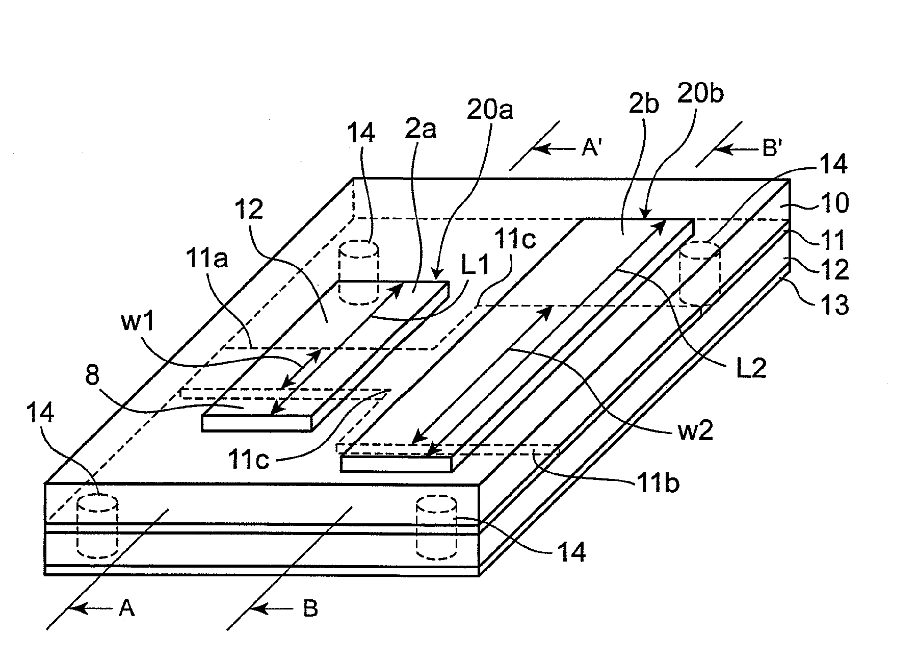
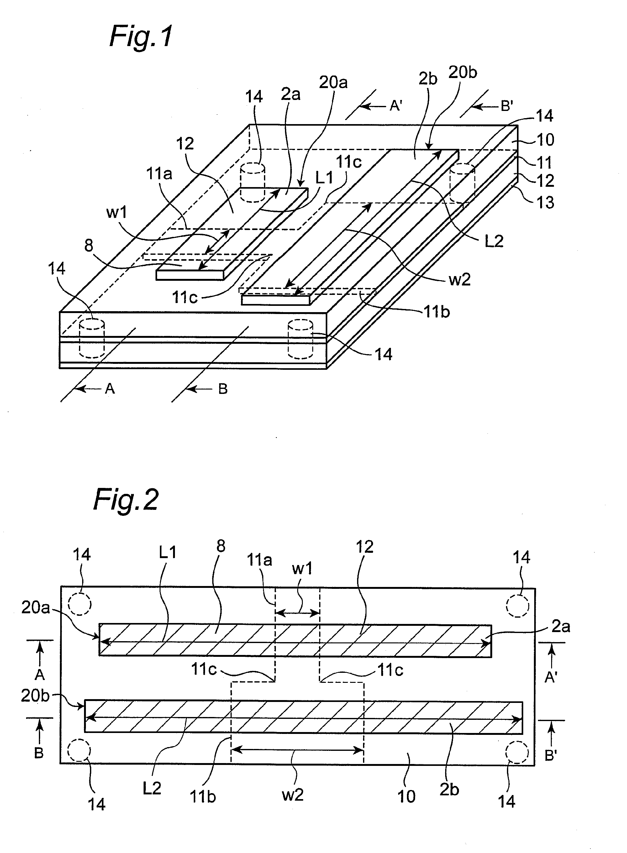
[0053]First of all, a differential transmission line according to one preferred embodiment of the present invention is described below with reference to FIGS. 1 to 4. FIG. 1 is a perspective view of a differential transmission line according to one preferred embodiment of the present invention, and FIG. 2 is a top view of the differential transmission line of FIG. 1.

[0054]Referring to FIGS. 1 and 2, the differential transmission line of the present preferred embodiment is constituted by including a dielectric substrate 10 of a parallel flat plate that has front surface and back surface which are formed in substantially parallel to each other, a grounding conductor 11 ...


PUM


Abstract

In a differential transmission line, a substrate has first and second surfaces parallel to each other, and a first grounding conductor is formed on the second surface of the substrate. A dielectric layer is formed on the first grounding conductor, and a second grounding conductor is formed on the dielectric layer. First and the second signal conductors are formed to be parallel to each other on the first surface of the substrate. The first signal conductor and the first and second grounding conductors constitutes a first transmission line, and the second signal conductor and the first and second grounding conductors constitutes a second transmission line. A slot is formed in the first grounding conductor to sterically intersect with the first and second signal conductors and to be orthogonal to a longitudinal direction thereof, and a connecting conductor is formed for connecting the first grounding conductor with the second grounding conductor.

Description

BACKGROUND OF THE INVENTION[0001]1. Field of the Invention[0002]The present invention relates to a differential transmission lines and, in particular, to a differential transmission line that transmits an analog high-frequency signal or a digital signal in a microwave band, a sub-millimeter wave band or a millimeter wave band.[0003]2. Description of the Related Art[0004]A differential signal transmission system, which has less radiation and is also robust to noises as compared with the single-ended signal transmission system that has been conventionally used, has been therefore increasingly used for high-speed signal transmissions.[0005]FIG. 12 is a top view of a prior art differential transmission line. FIG. 13 is a longitudinal sectional view along the line C-C′ of the differential transmission line of FIG. 12 showing an electric field vector Ee in an odd mode. FIG. 14 is a longitudinal sectional view along the line C-C′ of the differential transmission line of FIG. 12 showing an ...

Claims


Application Information

Patent Timeline
IPC IPC(8): H01P3/08
CPCH01P3/026H01P1/02H01P3/02
Inventor MINEGISHI, AKIRAYAMADA, TORUURIU, KAZUHIDESAWADA, SUSUMU
Owner PANASONIC CORP
Why Eureka
Try Eureka