Antenna device having wave collector

Inactive Publication Date: 2010-01-07
JOYMAX ELECTRONICS CO LTD
View PDF3 Cites 1 Cited by
  • Summary
  • Abstract
  • Description
  • Claims
  • Application Information

AI Technical Summary

Benefits of technology

[0010]The primary objective of the present invention is to provide an antenna device including a wave collector or w

Problems solved by technology

However, the typical antenna devices have no wave collector or wave collecting device to suitably collect the waves or signals such that the gain of the typical antenna devices may not be suitably increased.
However, simila

Method used


Image

  • Antenna device having wave collector
  • Antenna device having wave collector
  • Antenna device having wave collector

Examples


Example

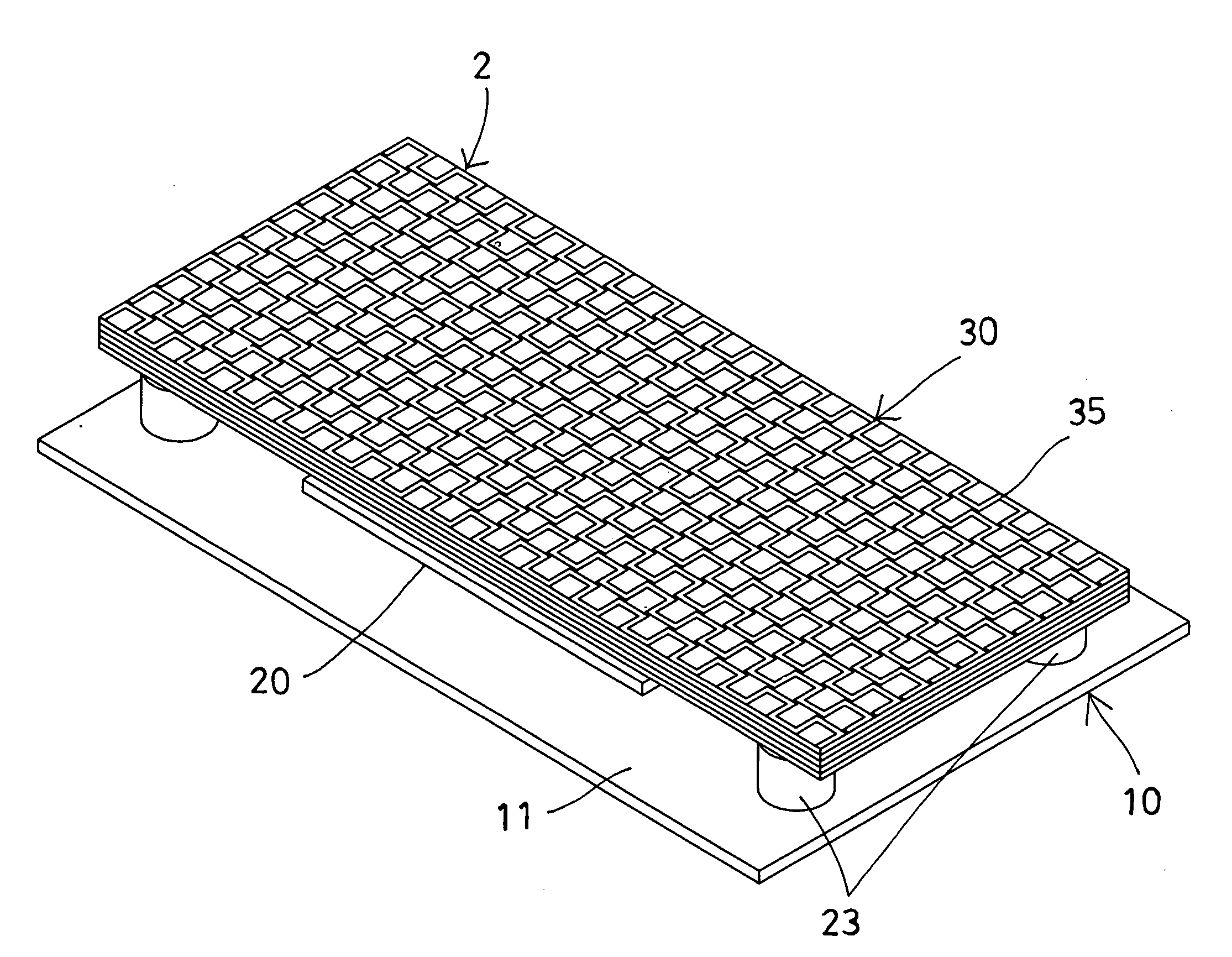
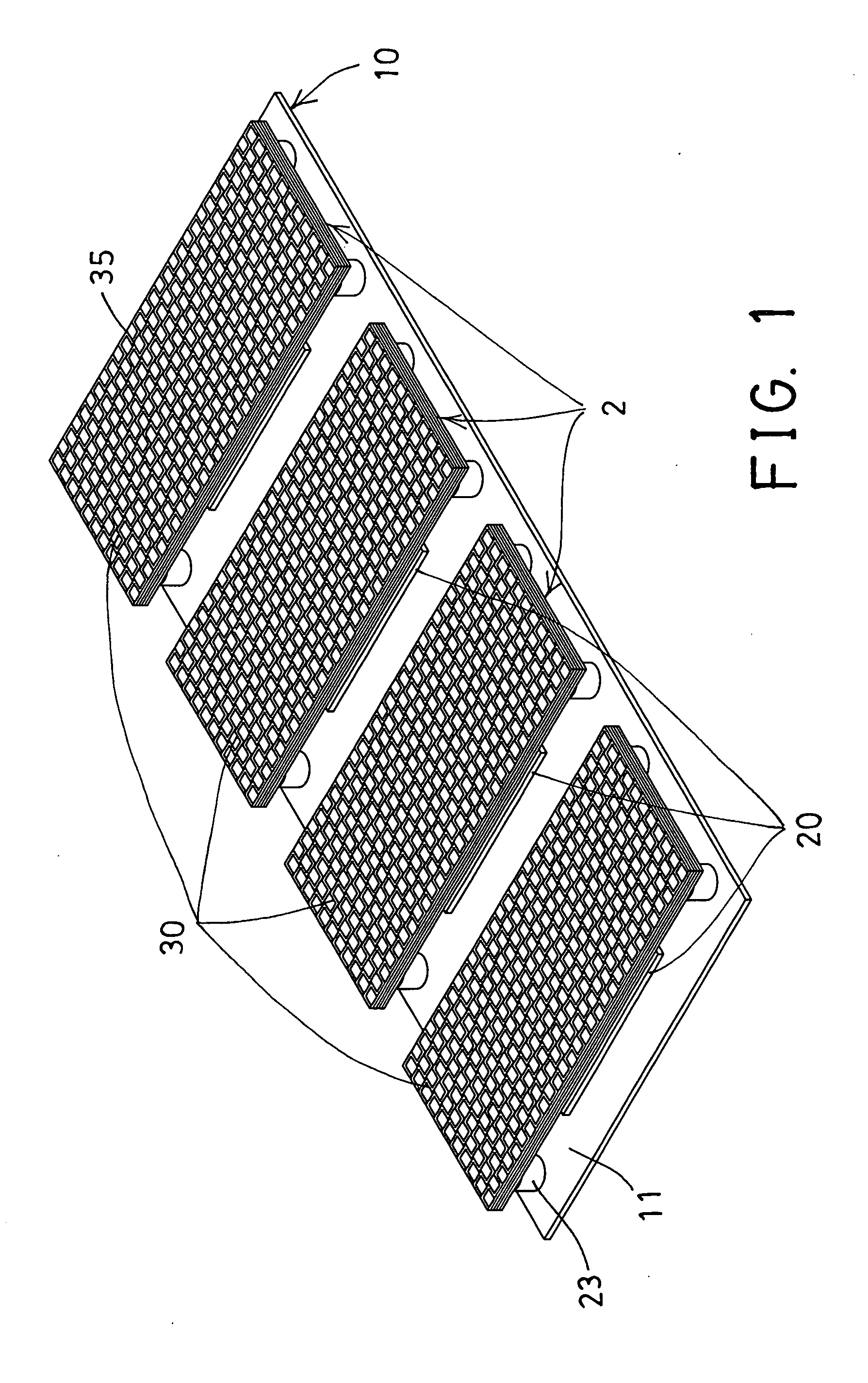
[0026]Referring to the drawings, and initially to FIG. 1, an antenna assembly in accordance with the present invention comprises a printed circuit board or an earth plate 10 including a grounded upper surface 11, and including a feed 12 (FIG. 5) provided or attached to the lower or bottom portion 13 of the earth plate 10 for transmitting or receiving waves or signals. One or more (such as four) antenna devices 2 are attached to or disposed on the earth plate 10.

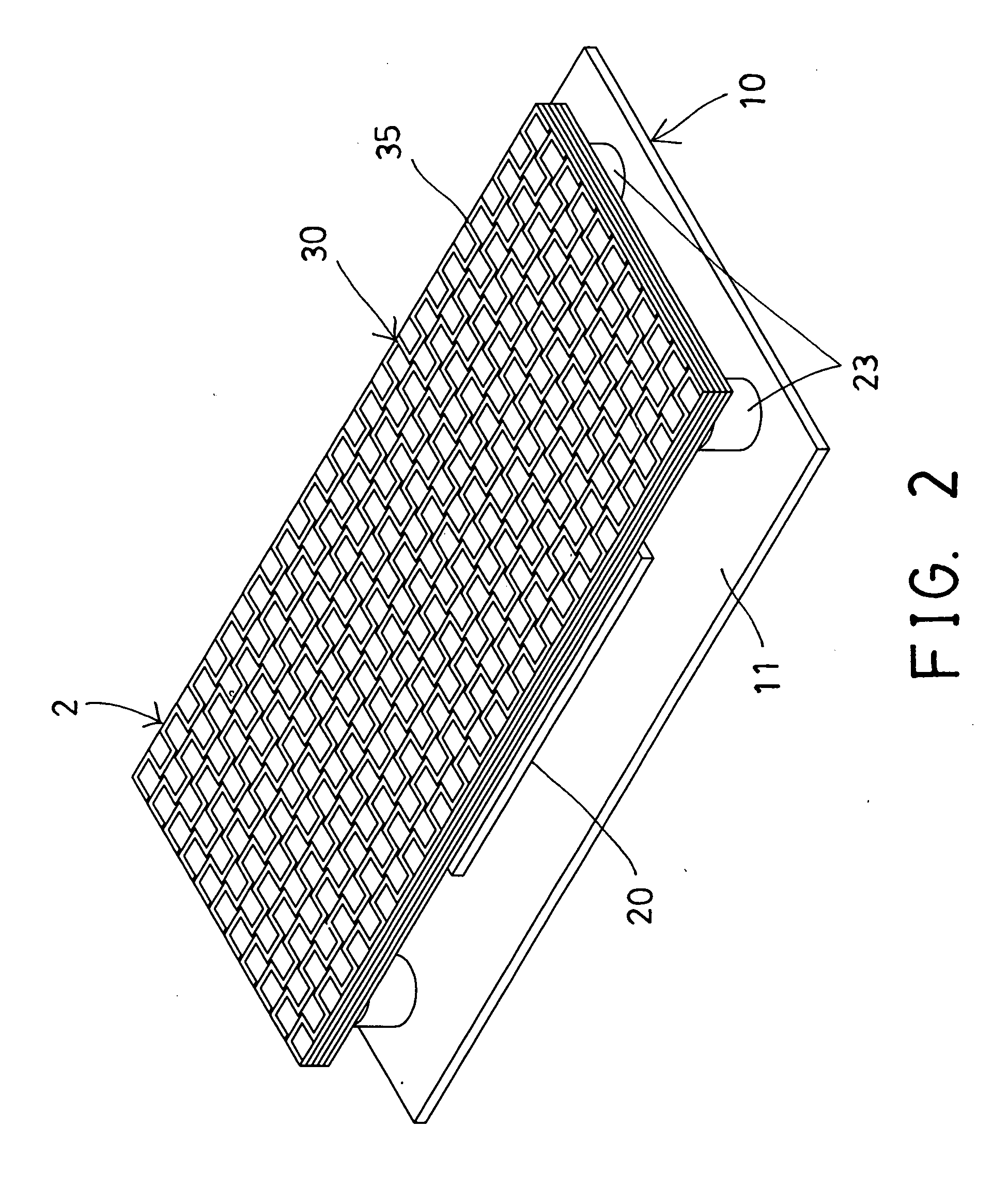
[0027]As shown in FIGS. 2-4, illustrated is one of the antenna devices 2 which includes an antenna member or radiator 20 attached to or disposed on the earth plate 10 with one or more insulators or spacers 21 and disposed at a distance essentially parallel to the earth plate 10 with the spacers 21, and includes a wave collector or wave collecting device or hood 30 attached to or disposed on the earth plate 10 with one or more insulators or spacers or pads 23 and disposed at a distance essentially parallel to the earth plate 1...


PUM


Abstract

An antenna device includes a radiator disposed on an earth plate with one or more spacers, and a hood disposed on the earth plate with one or more pads which include a height greater than that of the spacers for allowing the hood to be supported at a distance greater than the radiator, and the radiator is disposed between the hood and the earth plate and spaced from the hood and the earth plate. The hood includes one or more boards each having a pattern for collecting waves or signals, and a spacing panel disposed between the boards. The patterns of the boards are preferably arranged in different direction for suitably collecting the waves or signals and for increasing the gain of the antenna device.

Description

BACKGROUND OF THE INVENTION[0001]1. Field of the Invention[0002]The present invention relates to an antenna device, and more particularly to an antenna device including a wave collector or wave collecting device for suitably collecting the waves or signals and for increasing the gain of the antenna device.[0003]2. Description of the Prior Art[0004]Typical antenna devices comprise one or more radiators disposed on an earth plate or a printed circuit board for transmitting or receiving waves or signals and for allowing the radiators to transmit or to receive waves or signals or different resonant frequencies.[0005]For example, U.S. Patent Application Publication No. US 2001 / 0054979 A1 to Bahr et al., and U.S. Patent Application Publication No. US 2002 / 0104615 A1 to Lebaric et al. disclose two of the typical antenna devices each comprising a radiator disposed on an earth plate or a printed circuit board and disposed at a distance essentially parallel to the earth plate and conductively...

Claims


Application Information

Patent Timeline
IPC IPC(8): H01Q1/48H01Q9/04
CPCH01Q15/02H01Q15/0006
Inventor HU, WEI LONG
Owner JOYMAX ELECTRONICS CO LTD
Why Eureka
Try Eureka