Eureka AIR delivers breakthrough ideas for toughest innovation challenges, trusted by R&D personnel around the world.

Bi-directional optical-amplifier module

Inactive Publication Date: 2005-05-17
SAMSUNG ELECTRONICS CO LTD
View PDF17 Cites 6 Cited by
  • Summary
  • Abstract
  • Description
  • Claims
  • Application Information

AI Technical Summary

Benefits of technology

[0014]The present invention overcomes the above-described problems, and provides additional advantages by providing a bi-directional optical-amplifier module that is capable of obtaining an increased gain while suppressing the multiple reflection caused by the internal optical components.
[0015]One aspect of the invention is to provide a bi-directional optical-amplifier module having an inexpensive configuration.
[0016]Another aspect of the invention is to provide a bi-directional optical amplifier that is capable of preventing nonlinearity in a dispersion-compensating fiber while achieving stability in the dispersion-compensating fiber.

Problems solved by technology

However, a degradation in optical signals may result from the multiple-reflected light that is generated by Rayleigh-back scattering in the optical fiber and the optical reflection in the optical elements.
If the optical amplifiers were used, a further degradation of optical signals may occur due to the amplification of the reflected light.
However, it is difficult for those elements to be effectively incorporated in the conventional OAMs, as shown in FIGS. 1a to 1d.
In addition, as the bi-directional optical amplifiers BOA1 and BOA2 used in the optical-amplifier module are configured without using any isolator, the undesirable lasing or other unstable phenomena may occur.
However, this technique has a problem in that the optical-transmission system or optical-communication network may have a limited performance due to the multiple-reflection of optical signals that is caused by Rayleigh-back scattering or various reflections occurring in the optical fiber.
As a result, the gain of the optical amplifier is limited.

Method used


Image

  • Bi-directional optical-amplifier module
  • Bi-directional optical-amplifier module
  • Bi-directional optical-amplifier module

Examples


Embodiment Construction

[0026]In the following description, for purposes of explanation rather than limitation, specific details are set forth such as the particular architecture, interfaces, techniques, etc., in order to provide a thorough understanding of the present invention. For purposes of simplicity and clarity, detailed descriptions of well-known devices, circuits, and methods are omitted so as not to obscure the description of the present invention with unnecessary detail.

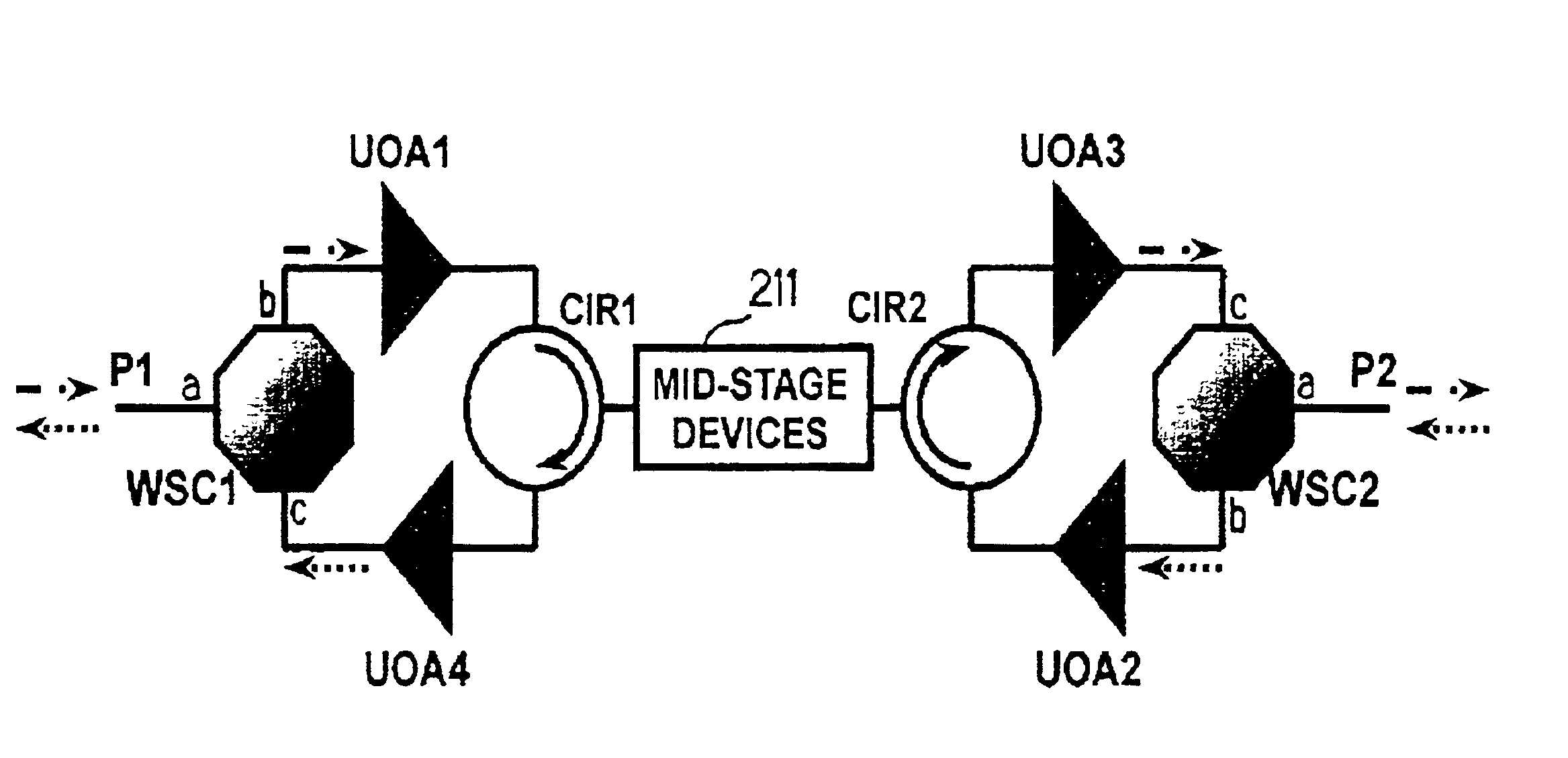
[0027]Referring to FIG. 2, the bi-directional optical-amplifier module (OAM) according to an embodiment of the present invention is illustrated. As shown in FIG. 2, the OAM receives, at its first input / output terminal P1, a downward optical signal traveling from left to right while outputting an upward optical signal traveling from right to left in an amplified state. The OAM also receives, at its second input / output terminal P2, the upward optical signal while outputting the downward optical signal in an amplified state.

[0028]Th...


PUM


Abstract

Disclosed is a bi-directional optical-amplifier module including first through fourth optical amplifiers, a mid-stage device for performing a desired signal processing for an upward or downward optical signal passing therethrough, a first optical-signal-path-setting device for supplying an optical signal inputted to a first input / output terminal of the bi-directional optical-amplifier module while outputting an optical signal outputted from the fourth optical amplifier to the first input / output terminal, a second optical-signal-path-setting device for supplying an optical signal inputted to a second input / output terminal of the bi-directional optical-amplifier module while outputting an optical signal outputted from the third optical amplifier to the second input / output terminal, a third optical-signal-path-setting device for outputting an optical signal outputted from the first optical amplifier to a first input / output terminal of the mid-stage device while supplying an optical signal outputted from the first input / output terminal of the mid-stage device to the fourth optical amplifier, and a fourth optical-signal-path-setting device for outputting an optical signal outputted from the second optical amplifier to a second input / output terminal of the mid-stage device while supplying an optical signal outputted from the second input / output terminal of the mid-stage device to the third optical amplifier.

Description

CLAIM OF PRIORITY[0001]This application makes reference to, incorporates the same herein, and claims all benefits accruing under 35 U.S.C. Section 119 from an application for “Bi-directional Optical-amplifier module,” filed in the Korean Industrial Property Office on Feb. 23, 2001 and there duly assigned Ser. No. 2001-9129.BACKGROUND OF THE INVENTION[0002]1. Field of the Invention[0003]The present invention relates to a bi-directional optical-amplifier module (OAM) for compensating optical signal loss caused by optical fibers or optical components in an optical transmission system, and more particularly to a multi-stage bi-directional OAM that is capable of suppressing the undesirable multiple reflections in an optical communication system.[0004]2. Description of the Related Art[0005]In a bi-directional optical transmission system, one or more multiplexed optical signals are transmitted in the opposite direction through a single optical fiber. As such, this type of bi-directional tr...

Claims


Application Information

Patent Timeline
IPC IPC(8): H04B10/17G02B6/42H01S3/30H01S5/50H01S3/10H04B10/00H04B10/2525H04B10/29H04B10/294H04B10/297H04J14/00H04J14/02
CPCH04B10/297G02B6/42
Inventor LEE, CHANG-HEEOH, YUN-JEHWANG, SEONG-TAEKKIM, HYUN DEOKSHIN, JEONG-HUNCHO, YUNHEE
Owner SAMSUNG ELECTRONICS CO LTD
Why Eureka
Eureka Blog
Learn More