Phase frequency detector circuit

Active Publication Date: 2014-07-10
NXP BV
View PDF5 Cites 2 Cited by
  • Summary
  • Abstract
  • Description
  • Claims
  • Application Information

AI Technical Summary

Benefits of technology

[0009]There is proposed an improvement to a phase-frequency detector circuit which may increase its gain by a factor of two without increasing charge pump

Problems solved by technology

From this, it can be seen that a higher value of Kpd will result in lower system noise.
Accordingly, the typical approach to increase Kpd is to increase ICP, nut th

Method used


Image

  • Phase frequency detector circuit
  • Phase frequency detector circuit
  • Phase frequency detector circuit

Examples


Example

[0027]Various techniques for improving the noise performance of a PLL are known, including: increasing the reference frequency, increasing the charge pump current and improving the noise performance of the charge pump. However, these known techniques exhibit various drawbacks. For example, a higher reference frequency may result in a more expensive overtone crystal, or may be incompatible with a given system reference frequency. Increasing the charge pump current may lead to higher spurious components, while decreasing it can facilitate smaller loop filter components and an eventual integration of the loop filter on chip. Improving the noise performance of the CP by using resistive (emitter / source) degeneration comes at the cost of available tuning range.

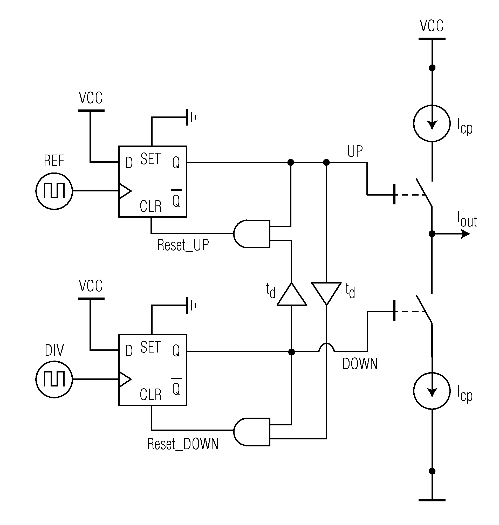
[0028]In an attempt to avoid the abovementioned drawbacks, the inventors have devised a concept for increasing the gain of the PFD / CP of a PLL without increasing the CP current.

[0029]The transfer function of the PFD / CP is the relati...


PUM


Abstract

A phase-frequency detector (PFD) circuit is disclosed. The PFD circuit includes a PFD portion adapted to detect frequency and phase difference of two input signals and to generate control signals according to the detected frequency and phase difference and a delay and reset portion adapted to delay the generated control signals, to generate reset signals for resetting the PFD portion based on a combination of the control signals and the delayed control signals, and to provide the generated reset signals to the PFD portion.

Description

FIELD OF THE INVENTION[0001]This invention relates to phase-locked loop (PLL) circuits, and more particular to a phase frequency detector (PFD) circuit for a PLL circuit.BACKGROUND[0002]Phase-locked loop (PLL) circuits are well-known in the field of communication systems. They are also they are also commonly used in frequency generating circuits (synthesizers) where quality (accuracy, temperature stability, jitter) of one oscillator is improved by locking to a second higher quality oscillator. The typical task of a PLL is to reproduce and track an original signal while removing as much of the noise as possible. Because of this, they are often used as narrow band filters in low noise satellites communications.[0003]A Phase-Frequency Detector (PFD) is a basic building block of a conventional PLL. Such a conventional PLL is shown in FIG. 1 and, in addition to a PFD, comprises a voltage-controlled oscillator (VCO), a frequency divider, a charge pump (CP) and a loop filter. Here, the CP ...

Claims


Application Information

Patent Timeline
IPC IPC(8): H03L7/089
CPCH03L7/0891H03D13/004
Inventor PRAAMSMA, LOUISIVANISEVIC, NIKOLA
Owner NXP BV
Why Eureka
Try Eureka