Turbine vane of a gas turbine

Active Publication Date: 2010-01-21
MTU AERO ENGINES GMBH
View PDF4 Cites 17 Cited by
  • Summary
  • Abstract
  • Description
  • Claims
  • Application Information

AI Technical Summary

Benefits of technology

[0008]The layer thickness of the thermal barrier coating can be adapted so exactly to the varying thermal stress of the surface regions of the turbine vane, and namely wit

Problems solved by technology

The disadvantage of this is that the turbine vanes can be quickly damaged on interfa

Method used


Image

  • Turbine vane of a gas turbine
  • Turbine vane of a gas turbine

Examples


Example

DETAILED DESCRIPTION OF THE DRAWINGS

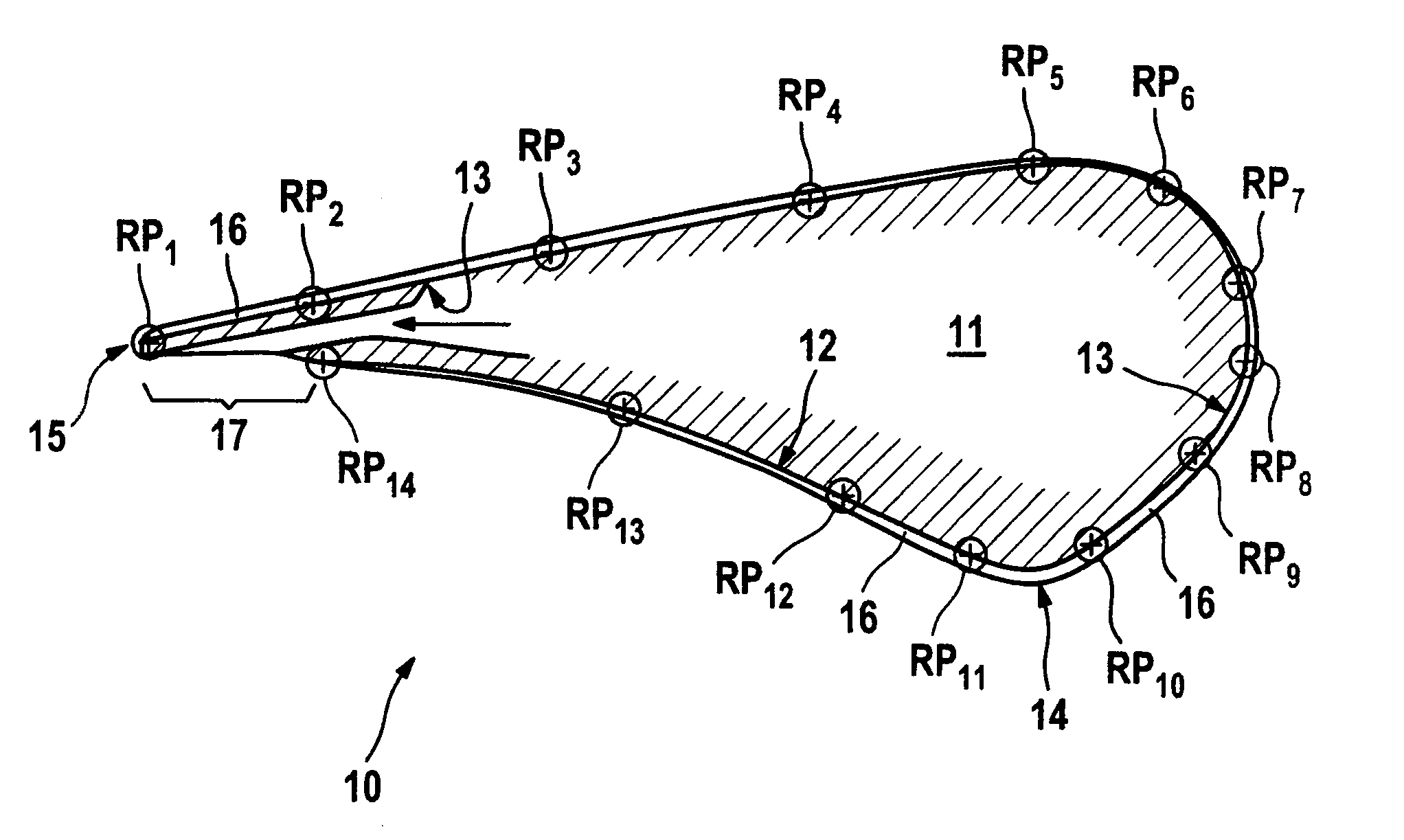
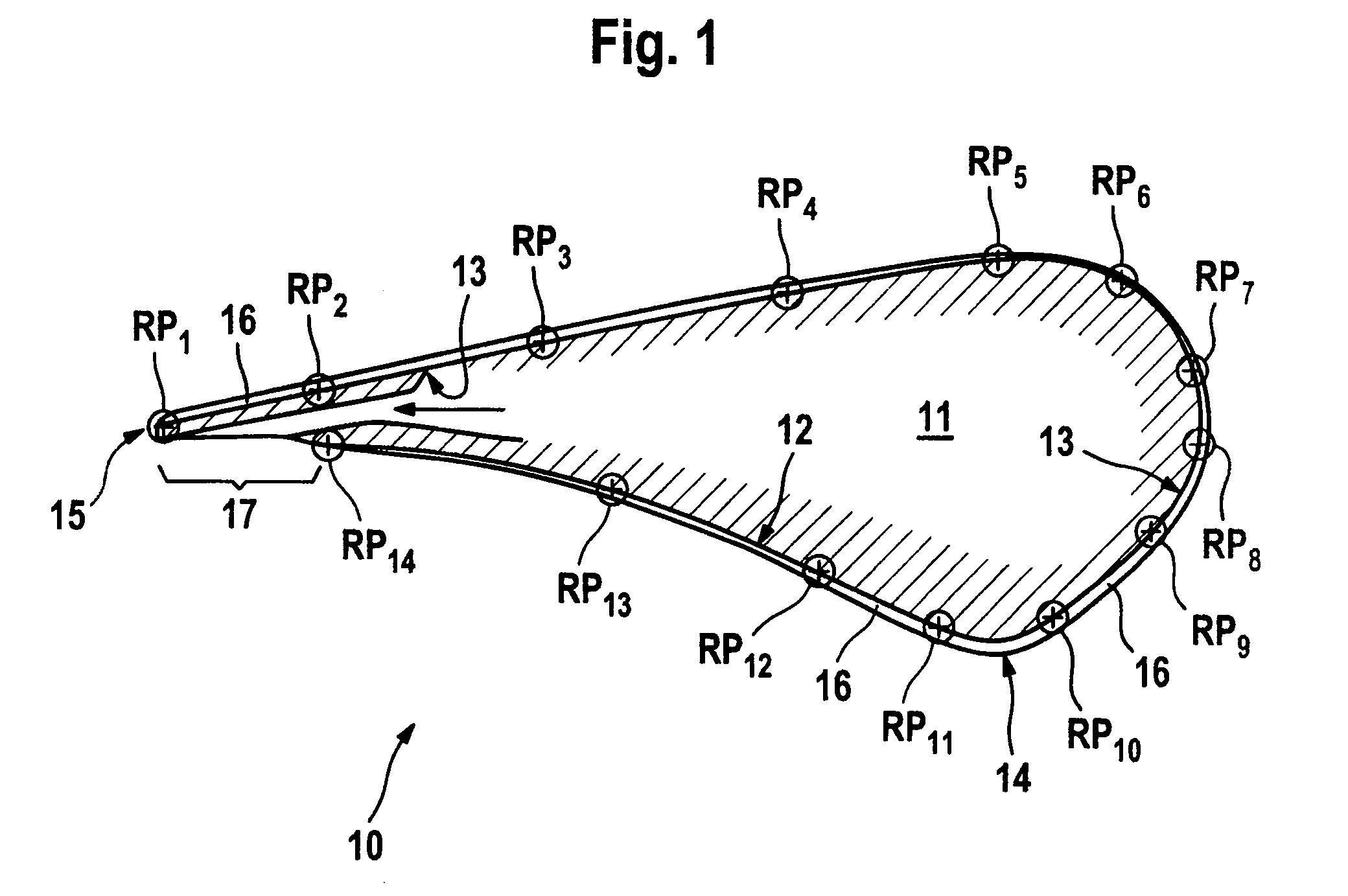
[0012]In the following, the present invention will be described using the example of a turbine vane 10, which is embodied as a stator-side guide vane. However, the invention is not limited to stator-side guide vanes, in fact the invention may also be used on rotor-side rotating vanes of a turbine.

[0013]FIG. 1 shows a schematic cross section through a turbine vane 10 embodied as a guide vane, wherein the turbine vane 10 comprises a vane base body 11, with an outer surface forming a pressure side 12, on the one hand, and a suction side 13, on the other. The pressure side 12 and the suction side 13 abut one another, on the one hand, in the region of a flow inlet edge 14 and, on the other hand, in the region of a flow outlet edge 15.

[0014]The vane base body 11 of the turbine vane 10 is coated with a thermal barrier coating 16 on its outer surface, and namely such that the thermal barrier coating 16 extends continuously or uninterruptedly at least larg...


PUM


Abstract

A turbine vane of a gas turbine, especially a gas turbine aircraft engine, is disclosed. The turbine vane includes a vane base body with an outer surface forming a suction side and a pressure side, the outer surface of the vane base body being at least partially coated with a thermal barrier coating. The thermal barrier coating extends continuously or uninterruptedly at least largely over the suction side and largely over the pressure side of the surface of the vane base body, with the layer thickness of the thermal barrier coating being variable or adjustable.

Description

BACKGROUND AND SUMMARY OF THE INVENTION[0001]This application claims the priority of International Application No. PCT / DE2007 / 001788, filed Oct. 6, 2007, and German Patent Document No. 10 2006 048 685.4, filed Oct. 14, 2006, the disclosures of which are expressly incorporated by reference herein.[0002]The invention relates to a turbine vane of a gas turbine, in particular of a gas turbine aircraft engine.[0003]Turbine vanes of a gas turbine, such as, for example, a gas turbine aircraft engine, are exposed to high temperatures and aggressive media during operation so that the turbine vanes are coated to protect surfaces with thermal barrier coatings among other things. For this purpose, known turbine vanes are coated in practice on an outer surface of their vane base body, which forms a suction side and a pressure side of the turbine vane, with a thermal barrier coating having a constant layer thickness. Turbine vanes known from practice are consequently provided with thermal barrier...

Claims


Application Information

Patent Timeline
IPC IPC(8): F01D9/02F01D5/28B05D7/00F01D5/18
CPCF01D5/18F01D5/288F01D9/041Y02T50/676F05D2260/941Y02T50/67Y02T50/673F05D2260/94Y02T50/60
Inventor ARRIETA, HERNANKLEINSTUECK, ROLFSTORM, PAULWIEDEMANN, PETER
Owner MTU AERO ENGINES GMBH
Why Eureka
Try Eureka