Clamping roller freewheel

Inactive Publication Date: 2010-02-18
SCHAEFFLER TECH AG & CO KG
View PDF5 Cites 1 Cited by
  • Summary
  • Abstract
  • Description
  • Claims
  • Application Information

AI Technical Summary

Benefits of technology

[0006]The object on which the invention is based is that of improving a clamping roller freewheel of the type specified in the preamble of claim 1 in such a way that idle running wear is prevented or at least reduced and therefore the service life of the

Problems solved by technology

One difficult aspect in structural terms is that of optimally designing the clamping springs which preload the clamping rollers in the direction of their clamping position and which likewise press the clamping rollers against the outer ring.
If the clamping springs are too strong, then, in overrunning operation, the outer ring grinds against the clamping rollers, which leads to wear of the clamping rollers.
So-called idle running wear generates an increase

Method used


Image

  • Clamping roller freewheel
  • Clamping roller freewheel
  • Clamping roller freewheel

Examples


Example

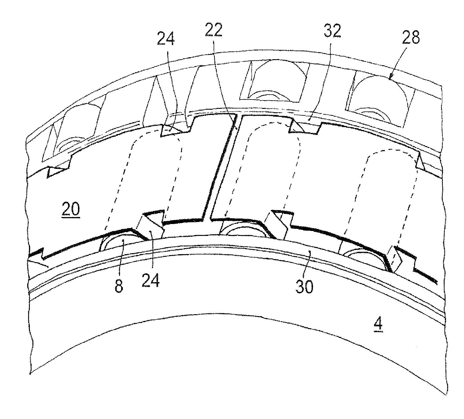
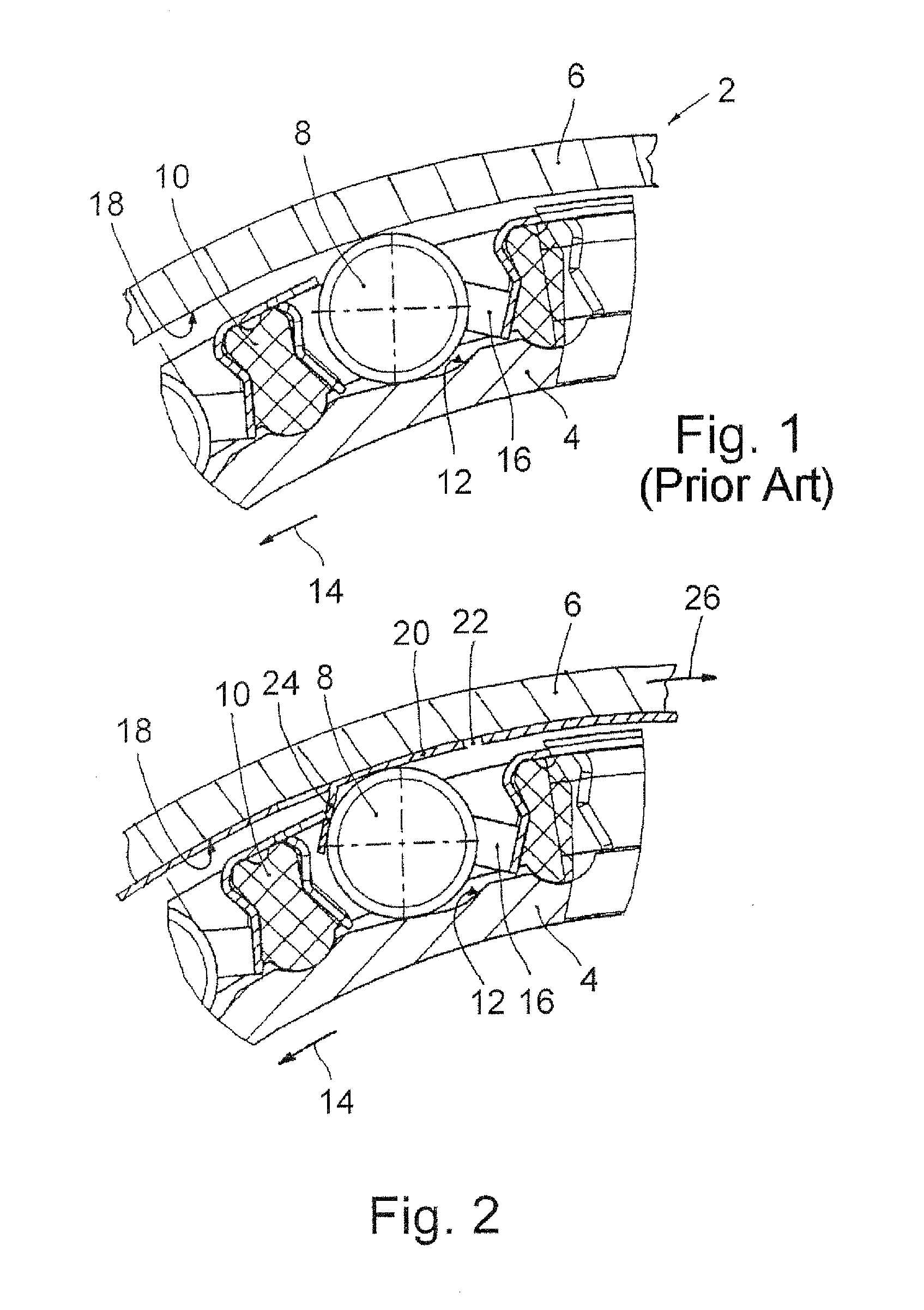
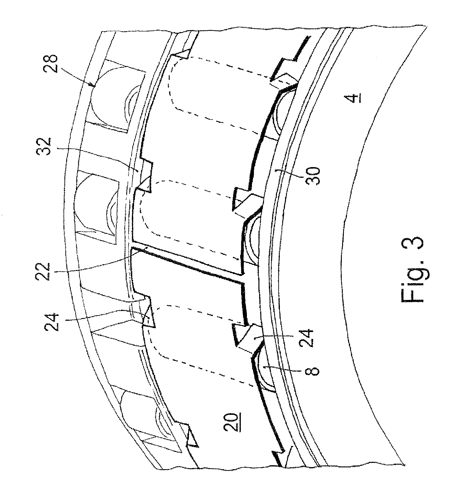
DETAILED DESCRIPTION OF THE DRAWINGS

[0023]The segment of a conventional clamping roller freewheel 2 illustrated in a cross section in FIG. 1 substantially comprises an inner ring 4, an outer ring 6 and clamping rollers 8 which are arranged between the inner ring and outer ring and are distributed over the circumference of the inner ring 4 and which are, for example, guided in a cage 10. As can be seen from FIG. 1, the clamping rollers 8 are assigned in each case one clamping ramp 12, with the clamping ramps 12 being designed such that the annular gap between the inner ring 4 and the outer ring 6 tapers in each case in the direction of the arrow 14. The clamping rollers 8 are preloaded slightly by associated freewheel springs 16 in the clamping direction, that is to say in the direction of the arrow 14, such that said clamping rollers 8 bear constantly against the clamping ramp 12 and against the inner circumference 18 of the outer ring 6.

[0024]When the inner ring 4, which serves, fo...


PUM


Abstract

A clamping roller freewheel, which has an inner ring, an outer ring and clamping rollers arranged between the inner ring and outer ring. The clamping rollers interact, in each case, with one clamping ramp formed on the outer circumference of the inner ring. The clamping rollers are surrounded by an elastically expandable protective ring which is concentric with respect to the freewheel axis. Retaining lugs prevent the protective ring from being driven in rotation by the outer ring in idle running operation. In this way, the outer ring is prevented from grinding against the clamping rollers, and the clamping rollers are prevented from being driven in rotation, with the resulting wear to the clamping ramps, in idle running operation.

Description

FIELD OF THE INVENTION[0001]The invention relates to a clamping roller freewheel having an inner ring and having an outer ring and also having clamping rollers arranged between said inner ring and outer ring, which clamping rollers interact with in each case one clamping ramp formed on the outer circumference of the inner ring.BACKGROUND OF THE INVENTION[0002]Clamping roller freewheels are a special type of the range of freewheel devices referred to generally as clamping body freewheels. Said clamping roller freewheels are used for example as overrunning clutches which, for example, decouple an originally driven branch of a drivetrain when said branch overruns the driving part of the drivetrain. Freewheel devices of said type are also used as non-return devices. The functional principle of all clamping body freewheels is that, in one drive direction, the clamping bodies become wedged and thereby produce a force-fitting connection between the inner ring and outer ring, while in the o...

Claims


Application Information

Patent Timeline
IPC IPC(8): F16C43/00
CPCF16D41/067
Inventor SMETANA, TOMAS
Owner SCHAEFFLER TECH AG & CO KG
Why Eureka
Try Eureka