Collecting tank and heat exchanger

Active Publication Date: 2011-07-05
BEHR GMBH & CO KG
View PDF36 Cites 1 Cited by
  • Summary
  • Abstract
  • Description
  • Claims
  • Application Information

AI Technical Summary

Benefits of technology

With preference, the hollow space is formed continuously in a tensile direction of the tie rod. With particular preference, a coolant is conducted through the hollow space, which coolant may also be ambient air, since the material temperatures can in this way be specifically lowered in the regions that are subjected to the greatest loading. In this way, the oxidative aging of the plastic is slowed, whereby the service life increases. Furthermore, less expensive plastics can also be used or, in certain cases, the use of plastics instead of aluminum becomes possible in the first place. The hollow space is preferably formed by a tube arranged in the tie rod, in particular with a substantially circular or oval cross section. In this case, it is also possible for a number of thin tubes to be arranged next to one another, formed separately or in one pi

Problems solved by technology

However, such a charge-air tank still leaves something to be desired.
In this case, however, productio

Method used


Image

  • Collecting tank and heat exchanger
  • Collecting tank and heat exchanger

Examples


Example

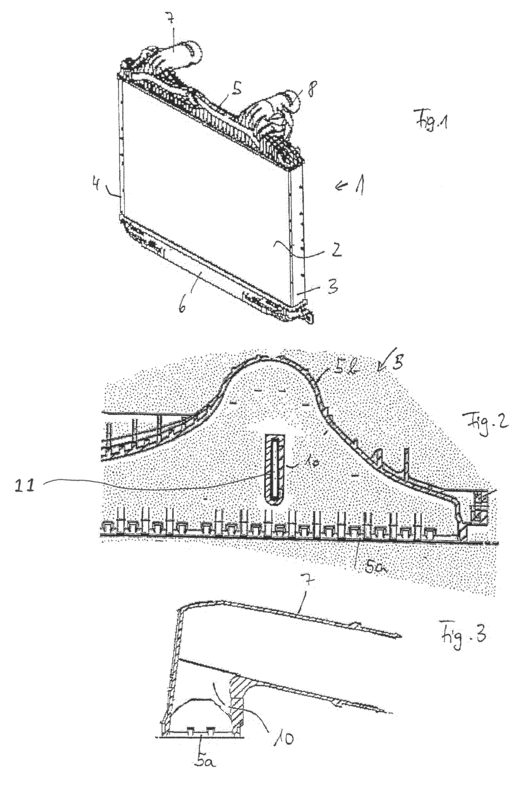
FIG. 1 shows a heat exchanger 1, such as a charge-air cooler with a tube-rib block 2, in which the individual tubes (not represented) are connected, such as for example soldered, to corrugated ribs arranged in between. Arranged to the sides of the tube-rib block 2 are side parts 3, 4. The tubes of the tube-rib block 2 are fluidically connected to collecting tanks 5, 6, so that the fluid, such as charge air, flowing into the one collecting tank 5 via the connecting piece 7 flows through part of the tubes of the tube-rib block to the second collecting tank 6, and from there via a further part of the tubes back to the first collecting tank, and from there can flow out through the connecting piece.

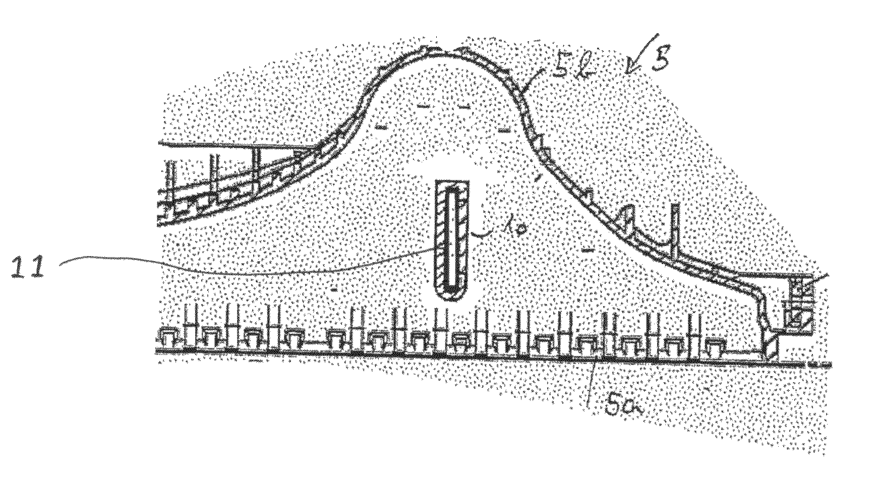
FIG. 2 shows a section through a collecting tank 5 with a tube sheet 5a and a cover 5b. Arranged in the region of the bell-shaped contour is a connecting piece 7, 8, which however is not visible in this representation. Arranged between a front wall of the cover of the collecting tank and a rea...


PUM


Abstract

The invention relates to a plastic charge air tank or coolant tank (5) comprising at least one tie rod (10) that is integrated thereinto and is connected thereto as a single piece or in a fixed manner. The tie rod (10) is provided with at least one continuous hollow space which extends along the longitudinal axis thereof.

Description

The invention relates to a collecting tank, in particular for a motor vehicle, and also to a heat exchanger.BACKGROUNDConventional, injection-molded plastic charge-air tanks, which are subjected to great loads, to be specific high temperatures and high pressures, are often formed in regions with particularly high loads with tie rods, which form a connection from one wall of the charge-air tank to the other. These tie rods are generally allowed for in the form in which the tank is produced and are injection-molded along with the charge-air tank from the same material. However, such a charge-air tank still leaves something to be desired.Therefore, EP 0 641 985 B1 discloses a heat exchanger tank with a number of reinforcing struts, which are formed separately from the heat exchanger tank and inserted into depressions, which extend between opposite walls of the heat exchanger tank, after the completion of the heat exchanger tank. In this case, however, production is relatively complex, ...

Claims


Application Information

Patent Timeline
IPC IPC(8): F28F9/02F28D1/02F28F21/06
CPCF28F9/02F28F21/067F28F2255/143F28F2225/08
Inventor KAMMLER, GEORGE
Owner BEHR GMBH & CO KG
Why Eureka
Try Eureka