
Industrial Textile for Manufacturing a Fibrous Web

Active Publication Date: 2021-12-09
VALMET TECH OY
View PDF23 Cites 1 Cited by
  • Summary
  • Abstract
  • Description
  • Claims
  • Application Information

AI Technical Summary

Benefits of technology

The patent describes a special industrial textile that has advantages for use in paper or board production. The text explains that the textile has different thickness yarns on both sides, which makes it easier to run and increases its lifespan. This feature helps to improve the performance of the textile and make it more durable.

Problems solved by technology

Owing to the single warp system, the wires are thin, but also susceptible to breaking.
As the dewatering elements of the paper machine wear down the fabric on the wear side, all yarns in the warp direction also wear down, and the risk of the fabric breaking increases.
In addition, the wear on the yarns makes the fabric unstable, which degrades the paper profiles.
As a result, the intersections remain under the surface of the wire, which may cause markings.
Internal wear occurs in SSB structures.
Internal wear occurs when the paper-side and the wear-side layers are not connected to each other closely enough, which results in the layers rubbing against each other.
In SSB structures, internal wear especially occurs in the intersections of the binding yarns.
The movement of the paper side and wear side against each other causes wear on the warp or weft yarns above and below the intersection of the binding yarns.
The wear changes the overlap of the layers in the direction of the warp and the permeability of the paper machine fabric deteriorates considerably.
The wear may be uneven, which means that the overlap of warp threads may vary over the width of the machine, causing profile issues in the paper.
As a result, more material is needed to manufacture the product, it is slower to weave and it becomes more expensive to manufacture.
The thickness of the paper machine fabric becomes a problem for certain types of fast paper machines.

Method used


Image

  • Industrial Textile for Manufacturing a Fibrous Web
  • Industrial Textile for Manufacturing a Fibrous Web
  • Industrial Textile for Manufacturing a Fibrous Web

Examples


Embodiment Construction

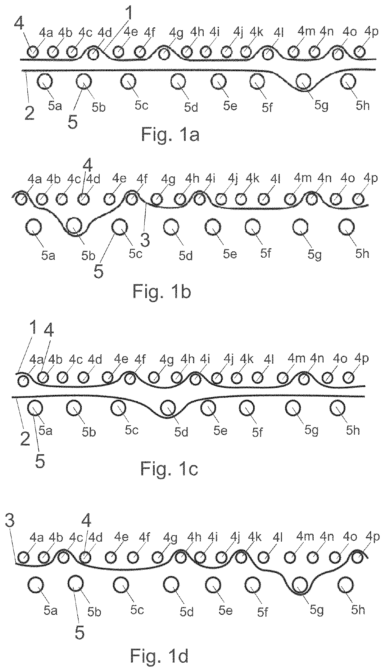
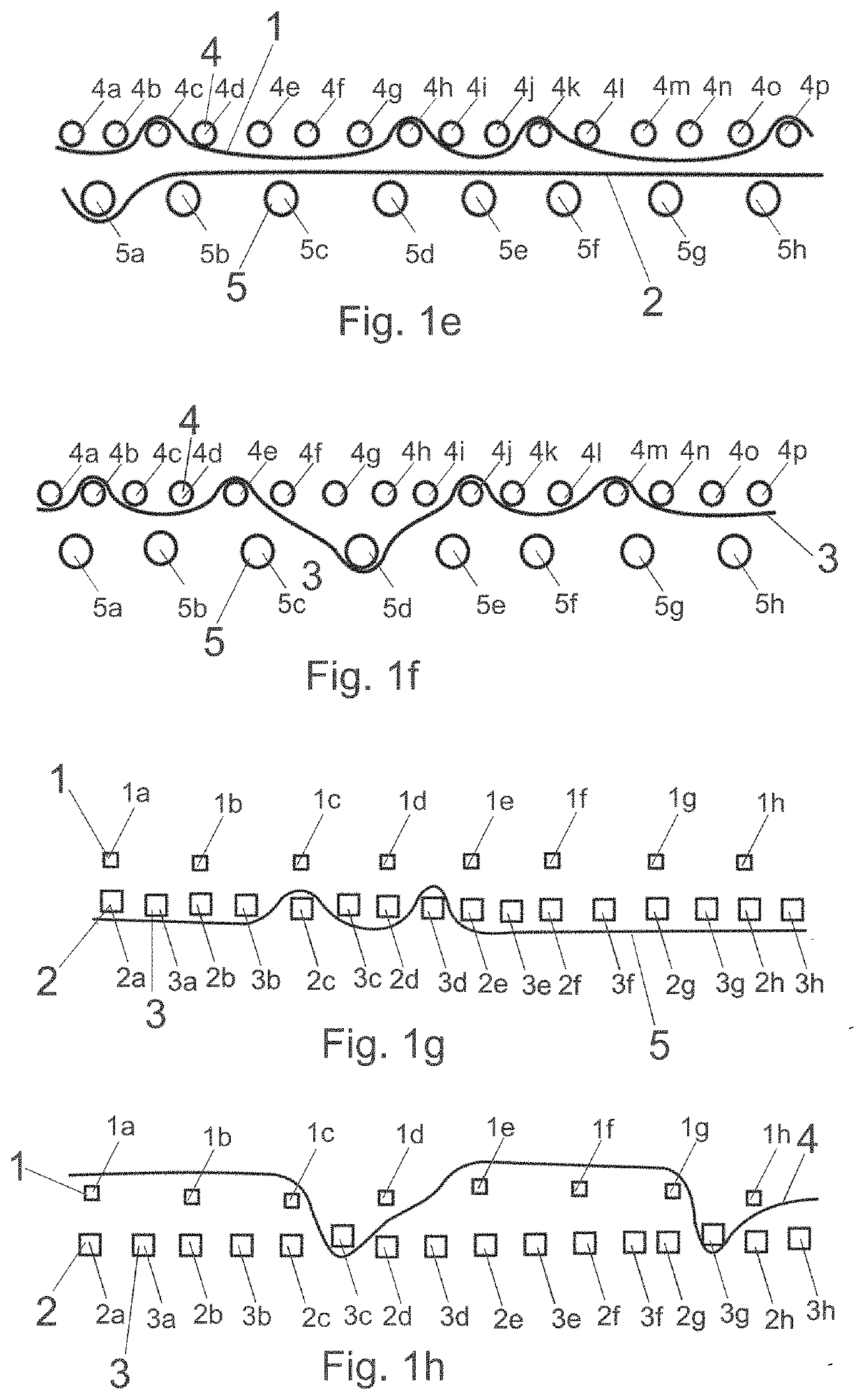
[0057]FIGS. 1a to 1h show a bind of an industrial textile 6. The industrial textile comprises first machine direction yarns 1, second machine direction yarns 2, third machine direction yams 3, first cross-machine direction yarns 4 and second cross-machine direction yarns 5.

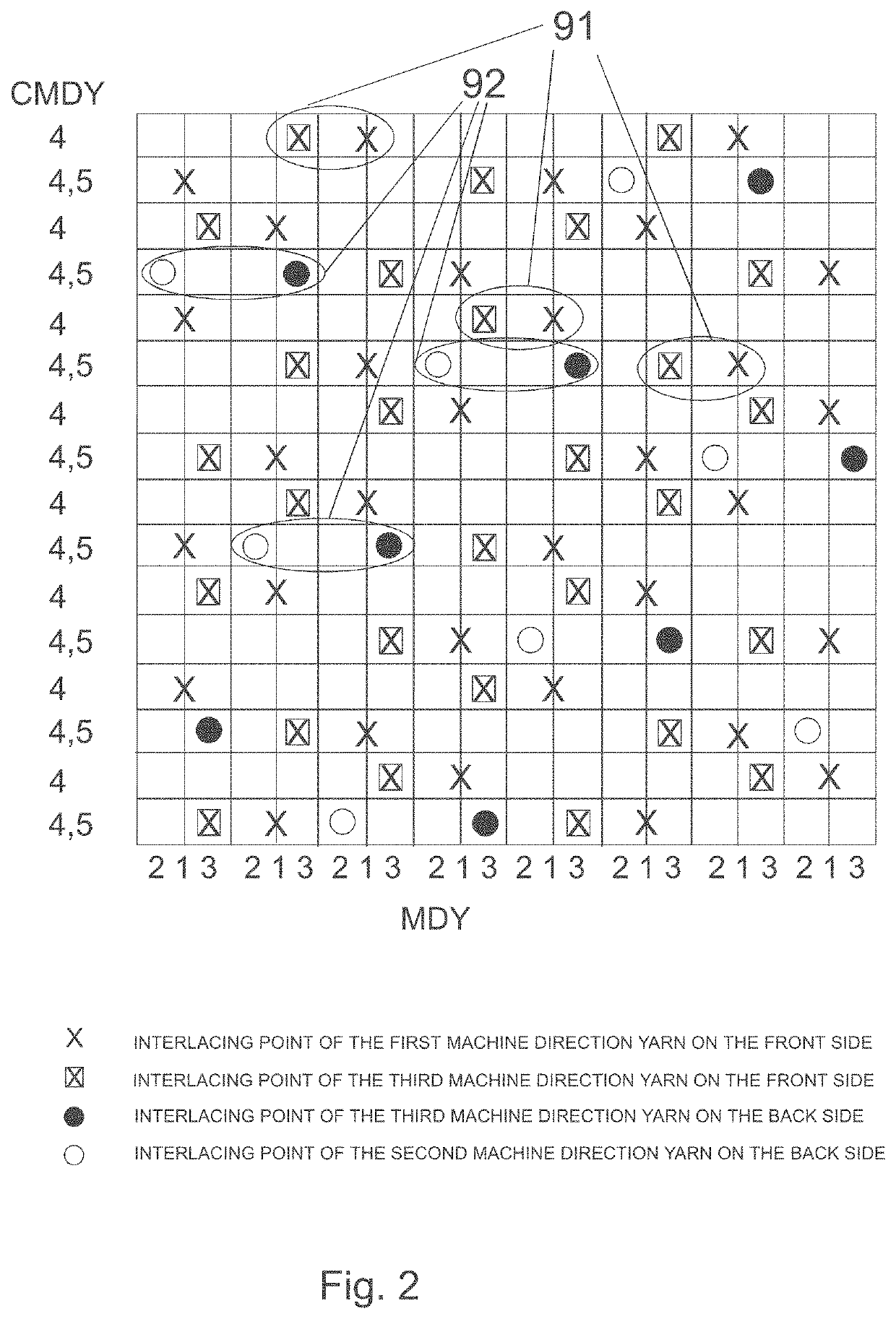
[0058]The first machine direction yarns 1 and the first cross-machine direction yams 4 form a first pattern. The first pattern has an offset of ±2. The second machine direction yams 2 and the second cross-machine direction yarns 5 form a second pattern. The second pattern has an offset of ±5. The third machine direction yarns 3, the first cross-machine direction yarns 4 and the second cross-machine direction yarns 5 form a third pattern. The third pattern has an offset of ±5. The interlacing points on the front side of the industrial textile has an offset of ±2.

[0059]The industrial textile is bound together by the third machine direction yarns 3, the first cross-machine direction yarns 4 and the second cross-machi...


PUM

PropertyMeasurementUnit
Timeaaaaaaaaaa
Timeaaaaaaaaaa
Timeaaaaaaaaaa

Abstract

An industrial textile (6) for manufacturing a fibrous web has first machine direction yarns (1) on the front side (7) which bind to first cross-machine direction yarns (4) in a first pattern, while second machine direction yarns (2) on the back side bind to second cross-machine direction yarns (5) in a second pattern. Third machine direction yarns (3) bind to the first cross-machine direction yarns (4) and the second cross-machine direction yarns (5) in a third pattern. The third pattern has at least one interlacing point (71) on the front side where one of the third machine direction yarns (3) passes over one of the first cross-machine direction yarns (4) and at least one interlacing point (72) on the back side (8) where the same third machine direction yarn (3) passes under one of the second cross-machine direction yarns (5).

Description

CROSS REFERENCES TO RELATED APPLICATIONS[0001]This application claims priority on Finnish Application No. FI 20205583, filed Jun. 4, 2020, the disclosure of which is incorporated by reference herein.STATEMENT AS TO RIGHTS TO INVENTIONS MADE UNDER FEDERALLY SPONSORED RESEARCH AND DEVELOPMENT[0002]Not applicable.BACKGROUND OF THE INVENTION[0003]The present invention relates to an industrial textile for manufacturing a fibrous web.[0004]Two-layer paper machine fabric structures, or double-layer wires, are widely known in the field. These structures have one warp system and two weft systems. The technology of a double-layer paper machine fabric has been described in U.S. Pat. No. 4,041,989, for instance. Owing to the single warp system, the wires are thin, but also susceptible to breaking. As the dewatering elements of the paper machine wear down the fabric on the wear side, all yarns in the warp direction also wear down, and the risk of the fabric breaking increases. In addition, the w...

Claims


Application Information

Patent Timeline
IPC IPC(8): D21F1/00D03D13/00
CPCD21F1/0036D03D13/004D03D11/00D03D21/00D03D13/00D21F1/0045
Inventor MARTIKAINEN, HANNURAUTIO, TANIASEPPÄNEN, MARITAIPALE, SEPPO
Owner VALMET TECH OY
Learn More