Bearing bush and production method for a bearing bush

Active Publication Date: 2021-09-23
TOKAI RUBBER IND LTD
View PDF0 Cites 1 Cited by
  • Summary
  • Abstract
  • Description
  • Claims
  • Application Information

AI Technical Summary

Benefits of technology

[0006]The present disclosure provides a bearing bush and a method for producing a bearing bush, wherein the fixing of a sleeve element and a cage element relative to one another is formed such that the service life of the bearing bush is increased, a

Problems solved by technology

The axial play between the fixing elements of the sleeve element and the cage element in conventional bearing bushes leads to an undesirable relative movement between the sleeve element and the cage element during use or under load, which promotes damage to the bearing bush over prolonged periods of use, and thus leads to a shortening of the service lives of conventional bearing bushes.
However, in order to reduce the axial play between the fixing elements of the sleeve element and the cage element

Method used


Image

  • Bearing bush and production method for a bearing bush
  • Bearing bush and production method for a bearing bush
  • Bearing bush and production method for a bearing bush

Examples


Example

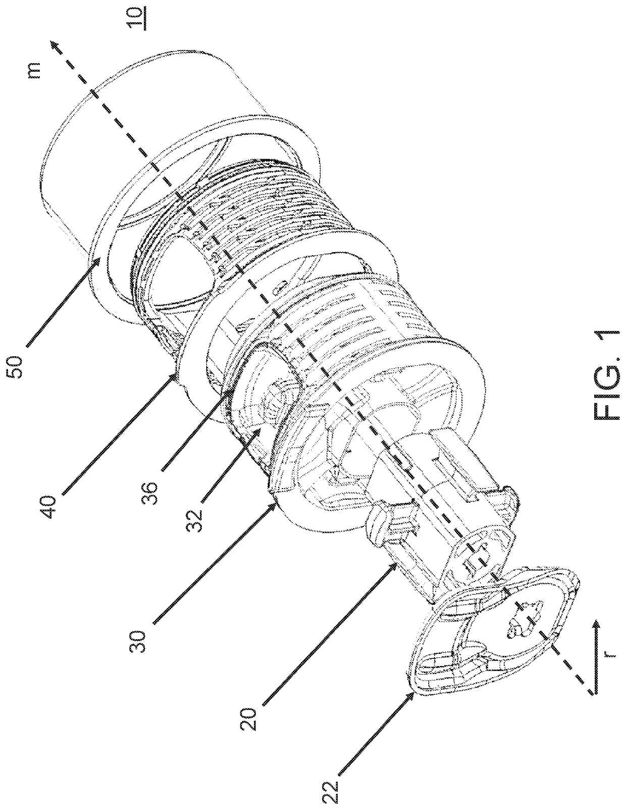
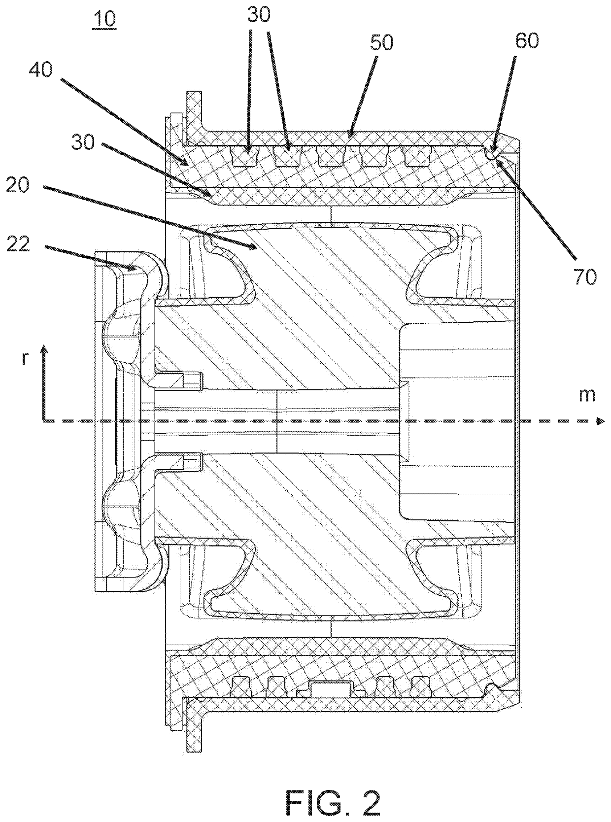
[0100]FIG. 1 is a perspective exploded view of a bearing bush 10, which is in the form of a hydraulic bearing bush in the present case. The bearing bush 10 here comprises a stop 22, a core 20, an elastomer element 30, a cage element 40 and a sleeve element 50. An axial direction m here corresponds substantially to the axis of the bearing bush 10. A radial direction r is perpendicular to the axial direction m and corresponds to a substantially radial direction of the bearing bush 10.

[0101]The elastomer element 30 is configured to connect the core element 20 and the cage element 40 elastically. The core element 20, the elastomer element 30 and the cage element 40 here form a pre-assembly element, which is pre-assembled or pre-manufactured in a step preceding the assembly of the bearing bush. The preassembly or pre-manufacturing step of the pre-assembly element that comprises the core element 20, the elastomer element 30 and the cage element 40 can comprise e.g. vulcanization.

[0102]In ...


PUM

PropertyMeasurementUnit
Ratioaaaaaaaaaa
Shapeaaaaaaaaaa
Radiusaaaaaaaaaa

Abstract

A bearing bush and a method for producing a bearing bush are provided. The bearing bush includes a core element, an elastomer element, a cage element and a sleeve element. The cage element is at least partially embedded in the elastomer element. The elastomer element elastically connects the cage element and the core element to each other. The core element, the cage element and the elastomer element form a pre-assembly element. One of the sleeve element and the cage element includes a protrusion. The other of the sleeve element and the cage element includes a groove, which is engageable with the protrusion, in an assembled state of the bearing bush. The pre-assembly element is fixed in the sleeve element. The protrusion and the groove form a two-point contact in a cross-section.

Description

CROSS REFERENCE TO RELATED APPLICATIONS[0001]This application claims the priority benefit of German Patent Application No. 10 2020 001 789.4, filed on Mar. 18, 2020. The entirety of the above-mentioned patent application is hereby incorporated by reference herein and made a part of this specification.TECHNICAL FIELD[0002]The disclosure relates to a bearing bush and a method for producing a bearing bush.BACKGROUND ART[0003]Conventional bearing bushes substantially includes a core element, an elastomer element, a cage element and a sleeve element, wherein the core element and the cage element are typically elastically connected by the elastomer body and form a pre-assembly element. In an assembled state of conventional bearing bushes, the sleeve element and the cage element or the pre-assembly element are fixed relative to one another by one or more flat contact surfaces, in particular by end faces that are perpendicular to an axis of the bearing bush.[0004]To achieve the fixing betwe...

Claims


Application Information

Patent Timeline
IPC IPC(8): F16F13/14
CPCF16F13/1445F16F13/1481F16C33/04F16C43/02F16F15/04F16C33/06F16C33/208F16C33/12F16F1/3842F16F2226/041F16F2228/001F16F2224/0241F16F2230/30
Inventor HAHN, KAYKHLISTUNOV, DMITRYMYSIN, ALEKSEY
Owner TOKAI RUBBER IND LTD
Why Eureka
Try Eureka