Display apparatus and production method thereof

a technology of display apparatus and production method, which is applied in the manufacture of electrode systems, electric discharge tubes/lamps, discharge tubes luminescent screens, etc., can solve the problems of adverse effect, difficulty in obtaining the opening width of current technology, and further reducing the size of conventional pixels, so as to achieve the effect of reducing the pixel aperture ratio and improving the resolution feeling

Active Publication Date: 2010-02-18
CANON KK
View PDF6 Cites 47 Cited by
  • Summary
  • Abstract
  • Description
  • Claims
  • Application Information

AI Technical Summary

Benefits of technology

[0014]It is an object of the present invention to provide a display apparatus which can display an image having higher resolution feeling, while solving the problem of patterning precision for sub pixels, which is difficult to obtain in production of a display apparatus in which one each of R sub pixel and B sub pixel, and two G sub pixels are disposed in one pixel, and a method of producing the display apparatus.
[0020]According to the present invention, the higher resolution feeling can be more improved without a reduction in pixel size. Even when the pixel size is reduced to advance the realization of high definition, the problem of the sub pixel patterning precision which is difficult to obtain in production can be solved. Therefore, the reduction in pixel aperture ratio can be minimized.

Problems solved by technology

However, when the conventional pixel size is to be further reduced, several adverse effects may be caused.
It is extremely difficult for the current technology to obtain the opening width by using a metal mask thin plate for etching.
However, particularly, in the case of the organic EL device, an adverse effect such as shortening of a life thereof, which corresponds to the increase in brightness, can be generated.
However, even when the size of the G sub pixel is reduced, it is unavoidable that the pixel size in the disposition illustrated in FIG. 16B becomes larger than a pixel size in an RGB stripe disposition illustrated in FIG. 16A (X01) because of the limit of the driving wiring pattern.
As a result, a problem of the reduction in pixel aperture ratio and a problem of the difficulty of sub pixel patterning occur.
Therefore, there is posed a problem that sub pixel patterning becomes more difficult because of the deviation of patterning position.

Method used


Image

  • Display apparatus and production method thereof
  • Display apparatus and production method thereof
  • Display apparatus and production method thereof

Examples


example 1

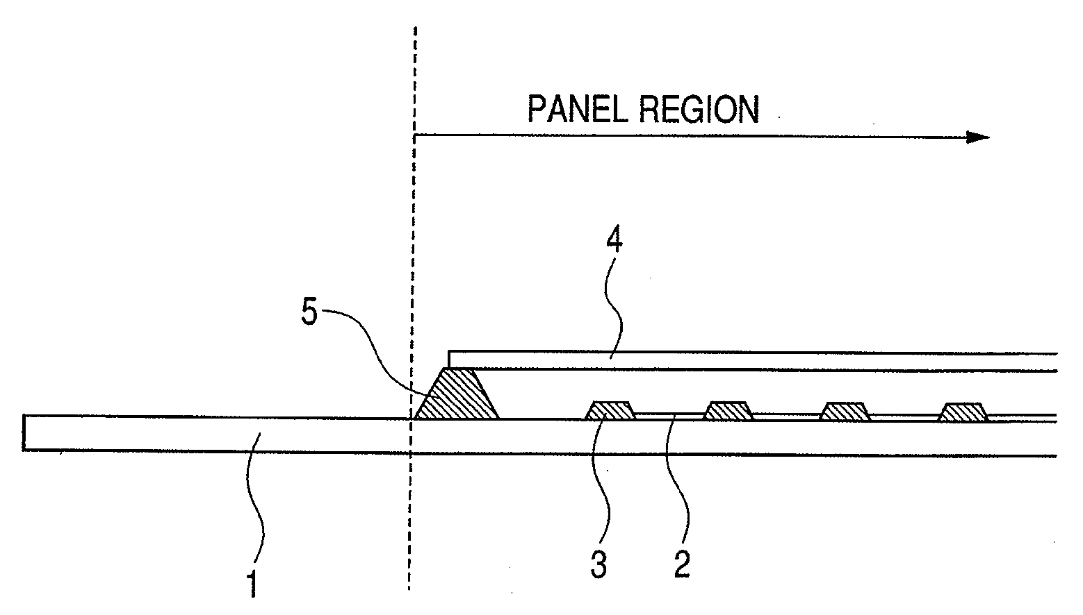
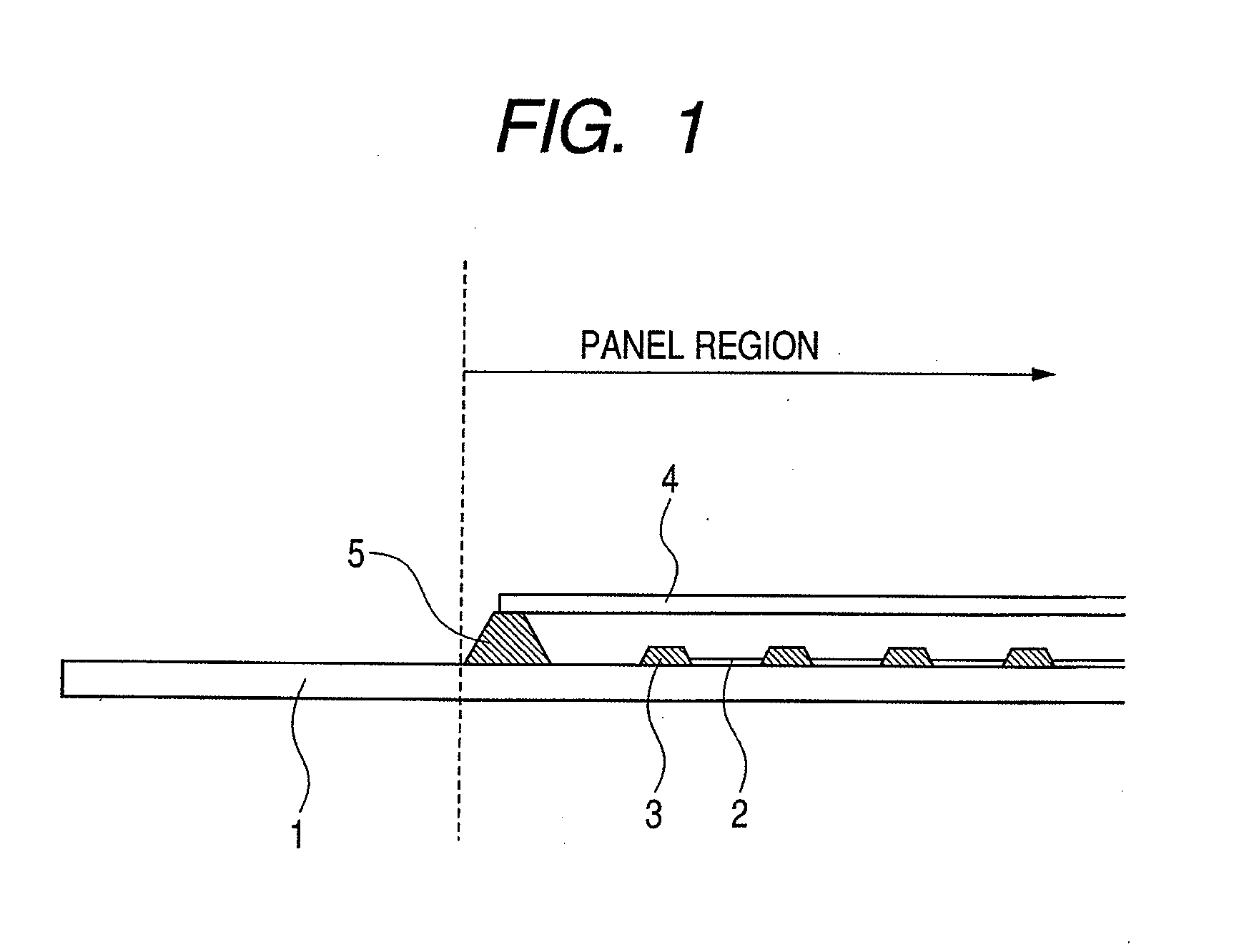
[0038]An organic EL display apparatus having a structure illustrated in FIG. 1 was produced.

[0039]Thin film transistors (TFTs), electrode wirings, and pixel electrodes, which are not shown, are formed in a matrix pattern on a substrate 1 illustrated in FIG. 1. One of glass, quartz, and a plastic film such as polyethylene terephthalate (PET), polycarbonate (PC), or polyethersulfone (PES) can be used for the substrate 1.

[0040]An organic compound for a light-emitting layer is formed on each of the pixel electrodes. An upper electrode is formed on the light-emitting layer. A protective film is formed on the upper electrode in some cases. In this example, the pixel electrodes, the organic compounds, and the upper electrodes, which are formed in a matrix pattern, compose a plurality of organic EL light-emitting portions (sub pixels) 2. The organic compounds for R, G, and B sub pixels are formed by evaporation to the organic EL light-emitting portions 2.

[0041]The respective organic EL ligh...

example 2

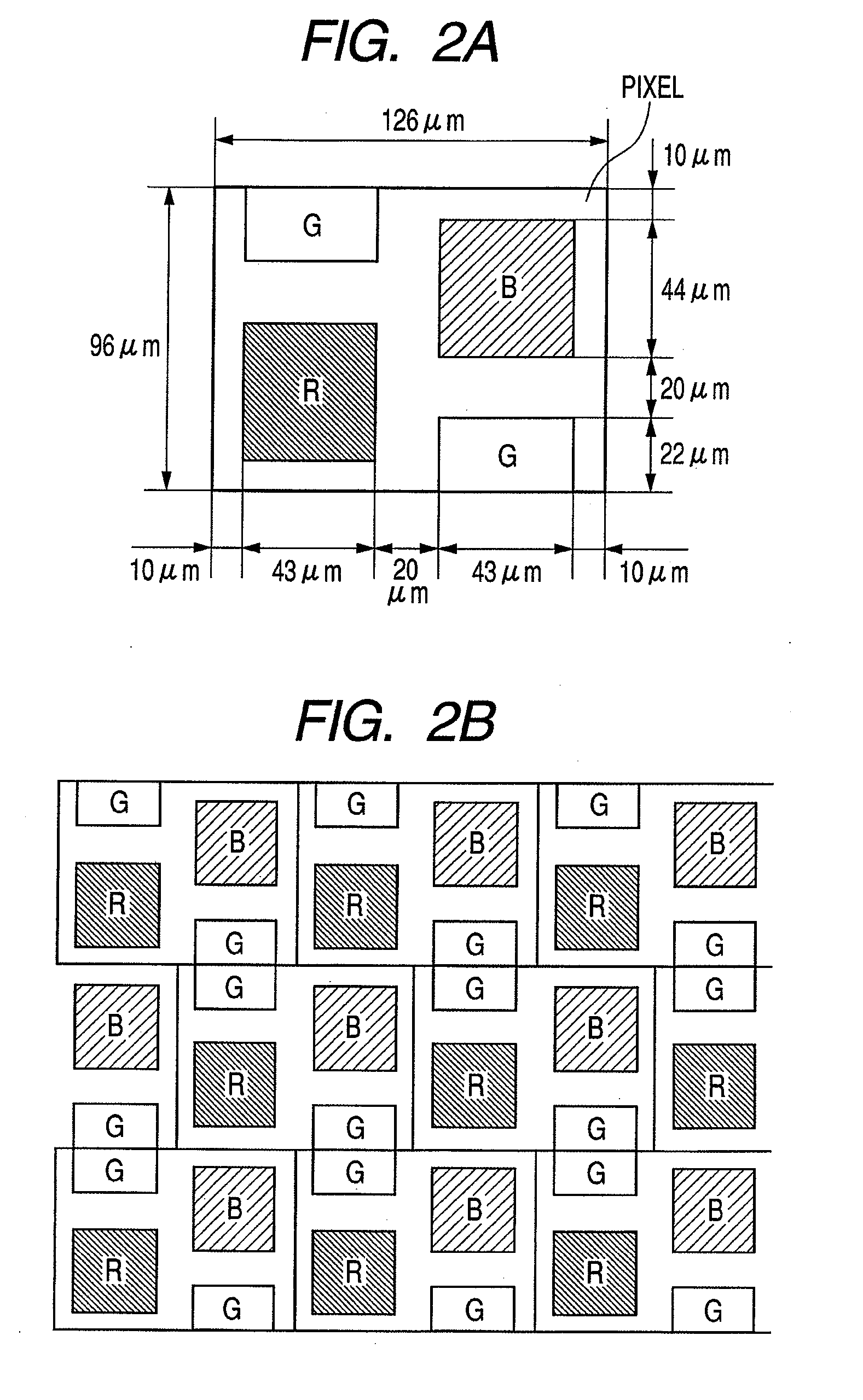
[0060]In order to confirm the superiority of the pixel and sub pixel disposition in the present invention, an image modeling a display panel having the pixel and sub pixel disposition in the present invention as illustrated in FIG. 6 was produced on a positive color film by exposure.

[0061]As illustrated in FIG. 6, the R sub pixel and the B sub pixel are disposed within each pixel in diagonal positions so as to partially overlap each other in any one of the two directions (vertical direction in this example) within the display surface. The two G sub pixels are disposed within each pixel in diagonal positions and distant from each other in the vertical direction.

[0062]With respect to other pixels adjacent to each other in the vertical direction, G sub pixels are adjacent to each other, an R sub pixel is adjacent to a B sub pixel, and a B sub pixel is adjacent to an R sub pixel. With respect to other pixels adjacent to each other in the other of the two directions within the display su...

example 3

[0081]In order to confirm the superiority of the pixel and sub pixel disposition in the present invention, an image modeling a display panel having the pixel and sub pixel dispositions in the present invention as illustrated in FIG. 9 was produced on a positive color film by exposure.

[0082]As illustrated in FIG. 9, with respect to the sub pixel disposition of pixels adjacent to each other in the vertical direction, line symmetry about a boundary line between the adjacent pixels as a symmetry axis is employed. In other words, the pixels adjacent to each other in the vertical direction have sub pixel dispositions reverse to each other in the vertical direction. With respect to the pixel disposition, the pixels adjacent to each other in the vertical direction are disposed in a grid pattern without offset of a pixel pitch in the horizontal direction.

[0083]In this example, the pixels adjacent to each other in the vertical direction are disposed in the grid pattern without offset of the p...


PUM


Abstract

There are provided a display apparatus that can display an image having higher resolution feeling while solving the problem of patterning precision for sub pixels which is difficult to obtain in production, and a production method thereof. The display apparatus includes a plurality of pixels disposed in two directions within a display surface and each having a sub pixel for emitting red light, two sub pixels for emitting green light, and a sub pixel for emitting blue light, wherein the sub pixel for emitting red light and the sub pixel for emitting blue light are disposed so as to partially overlap each other in one of the two directions, and the two sub pixels for emitting green light are disposed distant from each other in the one direction, wherein for the pixels adjacent to each other in the one direction, the sub pixels for emitting green light are adjacent to each other, and the sub pixel for emitting red light and the sub pixel for emitting blue light are adjacent to each other, and wherein the pixels adjacent to each other in the other of the two directions have the same sub pixel disposition.

Description

TECHNICAL FIELD[0001]The present invention relates to a display apparatus and a production method thereof.BACKGROUND ART[0002]According to a color display apparatus which is currently widely used, three primary colors (red (R), green (G), and blue (B)) are employed as one set and light quantities of the respective colors are adjusted to perform additive color mixing, thereby realizing color display.[0003]Display is obtained as a group including light emission portions and non-light emission portions in a plurality of pixels. Each of the pixels has a sub pixel for emitting a red color (hereinafter, referred to as R sub pixel), a sub pixel for emitting a green color (hereinafter, referred to as G sub pixel), and a sub pixel for emitting a blue color (hereinafter, referred to as B sub pixel), that is, sub pixels for three primary colors. Various three-primary-color disposition methods have been proposed up to now. Known dispositions are as follows. For example, as illustrated in FIG. 1...

Claims


Application Information

Patent Timeline
Patent Type & Authority Applications(United States)
IPC IPC(8): H01J1/62H01J9/00
CPCH01L27/3211H10K59/352H10K59/353
Inventor KARAKI, TETSUYAMORI, HIDEOISOBE, RYUICHIRO
Owner CANON KK
Why Eureka
Try Eureka