Organic el display apparatus

A display device, an organic technology, applied in the direction of static indicators, instruments, etc., can solve problems such as difficult to use lens arrays, achieve the effects of improving light utilization efficiency, reducing manufacturing costs, and preventing the increase of parasitic capacitance

Inactive Publication Date: 2012-05-30
CANON KK
View PDF6 Cites 12 Cited by
  • Summary
  • Abstract
  • Description
  • Claims
  • Application Information

AI Technical Summary

Problems solved by technology

However, in this case, it is difficult to use a structure in which a lens array is provided on an organic EL device

Method used


Image

  • Organic el display apparatus
  • Organic el display apparatus
  • Organic el display apparatus

Examples


Embodiment Construction

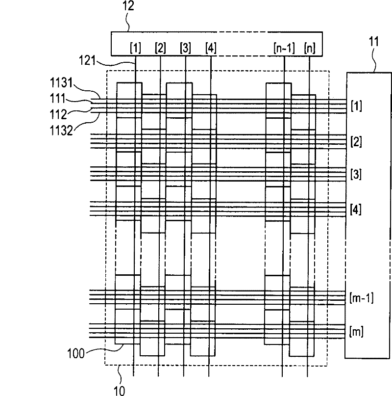
[0020] Hereinafter, embodiments of the present invention will be described in detail with reference to the accompanying drawings. figure 1 is a plan view schematically showing the structure of an organic electroluminescence display device (organic EL display device) according to an embodiment of the present invention. Such as figure 1 As shown, the organic EL display device of this embodiment includes a display area 10 in which a plurality of pixels 100 are arranged in a matrix of (m rows)×(n columns), and a row control circuit 11 and a column control circuit arranged around the display area 10 12. Here, "m" and "n" are natural numbers. The pixel circuit of each pixel 100 in the display area includes an organic EL device and a transistor (for example, a thin film transistor (TFT)) for controlling current to be supplied to the organic EL device. The arrangement of sub-pixels of each pixel 100 is described later. In addition, an organic EL device means a structure including ...


PUM


Abstract

Provided is an organic EL display apparatus in which, depending on a situation in which a user uses the organic EL display apparatus, display with high light use efficiency and high front luminance (luminous efficiency)or display with large view angle is selectable. Pixels each include subpixels having different optical characteristics from each other, and the pixels and the subpixels are respectively arranged in a staggered pattern. Further, the subpixels are independently controlled.

Description

technical field [0001] The present invention relates to an organic EL display device using an organic electroluminescent (EL) device. Background technique [0002] In an organic EL display device, a plurality of pixels each including an organic EL device are arranged in a matrix on a substrate. In each of the pixels, an organic EL device is connected in series with a driving thin film transistor (TFT) for driving the organic EL device and a power supply line for supplying power to the organic EL device. The organic EL device emits light in response to power supplied from a power supply line, and the emitted light is emitted outside the organic EL display device. [0003] As one of the problems of organic EL devices, low light extraction efficiency is known. The reason for this is that, in the organic EL device, light is emitted from the light-emitting layer at various angles, and thus a large amount of total reflection components are generated at the interface between the ...

Claims


Application Information

Patent Timeline
Patent Type & Authority Applications(China)
IPC IPC(8): G09G3/32
CPCG09G2300/0814G09G2300/043G09G2320/02G09G2320/028G09G3/3233G09G2300/0819G09G2300/0426
Inventor 玉木顺也森山孝志佐藤信彦
Owner CANON KK
Why Eureka
Try Eureka