Light source device, display device and reflection sheets for use therewith

a technology of display device and light source device, which is applied in the direction of static indicating device, lighting and heating apparatus, instruments, etc., can solve the problems of uneven luminance, uneven brightness from the emitting surface of the light guide plate, uneven luminance, etc., and achieve the effect of increasing the front luminance of the device, reducing the uneven luminance, and low cos

Inactive Publication Date: 2006-06-20
TWITTER INC
View PDF8 Cites 12 Cited by
  • Summary
  • Abstract
  • Description
  • Claims
  • Application Information

AI Technical Summary

Benefits of technology

[0011]It is another object of the present invention to provide a backlight unit display device capable of increasing the front luminance thereof while reducing unevenness in luminance compared to a conventional backlight unit device using a white reflection sheet.
[0012]It is still another object of the present invention to provide a display device of the type defined herein which can be produced relatively expeditiously and thus at relatively low cost to the purchaser thereof.

Problems solved by technology

However, the inventors of the present invention have discovered that a problem of unevenness in luminance occurs when a silver-layered reflection sheet is used for the sidelight type backlight unit.
Moreover, even if the back of the frame does not have the openings, the unevenness in luminance is sometimes recognized because the reflection sheet may be warped.
In a backlight unit in which a pattern of concave / convex structural portions are formed on the guide plate and a silver reflection sheet is combined with such structural portions on the back of the light guide plate, unevenness in brightness from the emitting surface of the light guide plate resulted.
Moreover, the problem of uneven luminance owing to the aforementioned press by a finger was more serious, especially when using a downward-facing prism sheet (as opposed to an upward-facing prism sheet).
However, it was also discovered that two problems were caused by interposing such a transparent sheet in such a manner.
Another is a problem of a “bright line”.
However, neither of these embodiments appear to consider unevenness in luminance which occurs when using a metal reflection sheet.

Method used


Image

  • Light source device, display device and reflection sheets for use therewith
  • Light source device, display device and reflection sheets for use therewith
  • Light source device, display device and reflection sheets for use therewith

Examples


Embodiment Construction

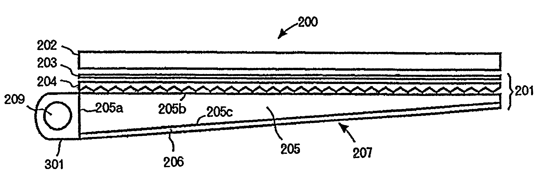
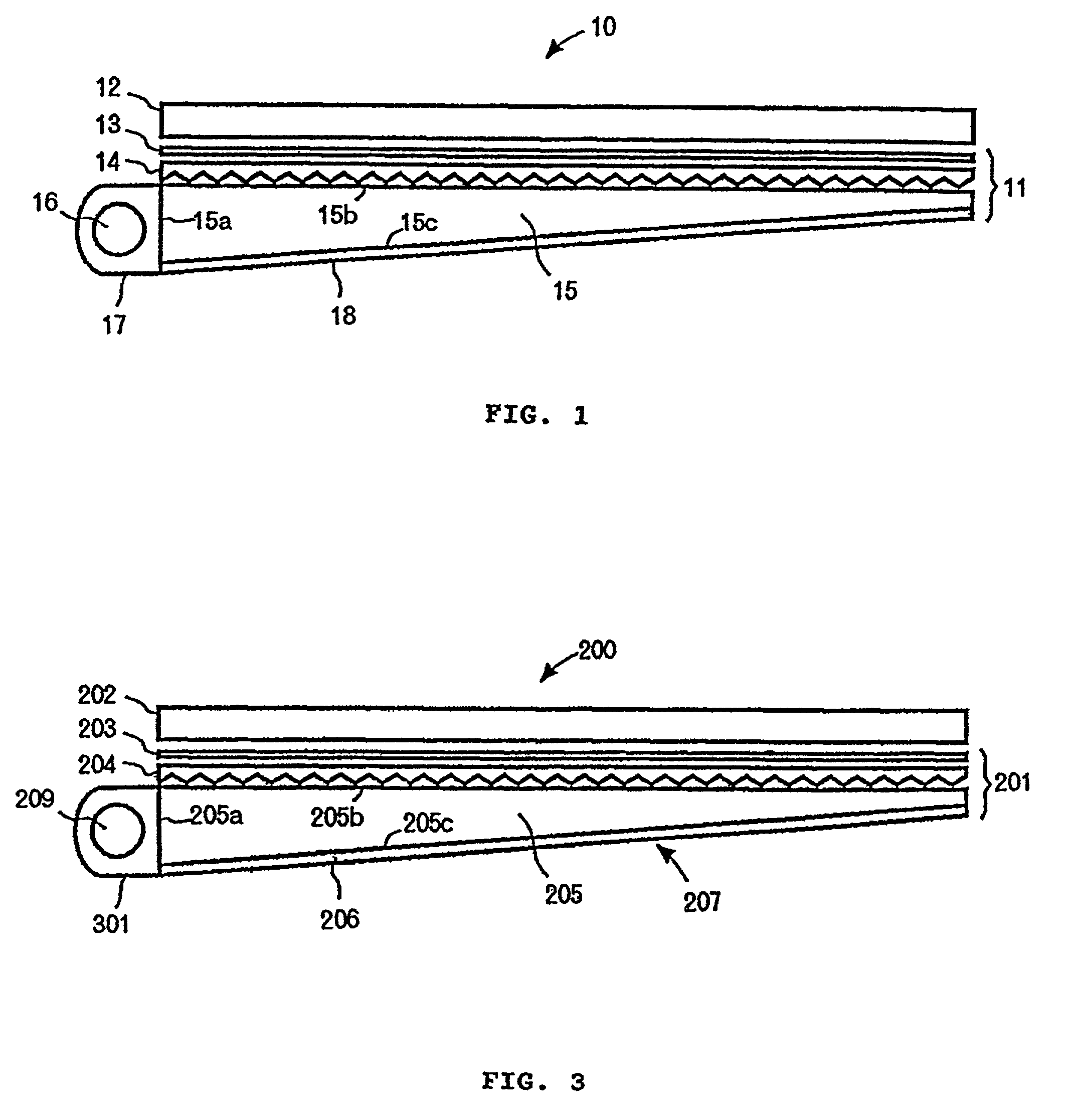
[0028]In a backlight unit according to one embodiment of this invention, a plurality of spacers are arranged between a light guide plate and a reflection sheet located on a back thereof. Even if the reflection sheet is pressed, a constant clearance is maintained between the back of the light guide plate and the reflection sheet by these spacers. It is thus possible to reduce unevenness in luminance on the surface of the backlight unit. Hereinafter, description will be made of a liquid crystal display device. The respective drawings are for illustrating this particular device, but it is understood that the invention is not limited to those of the liquid crystal type.

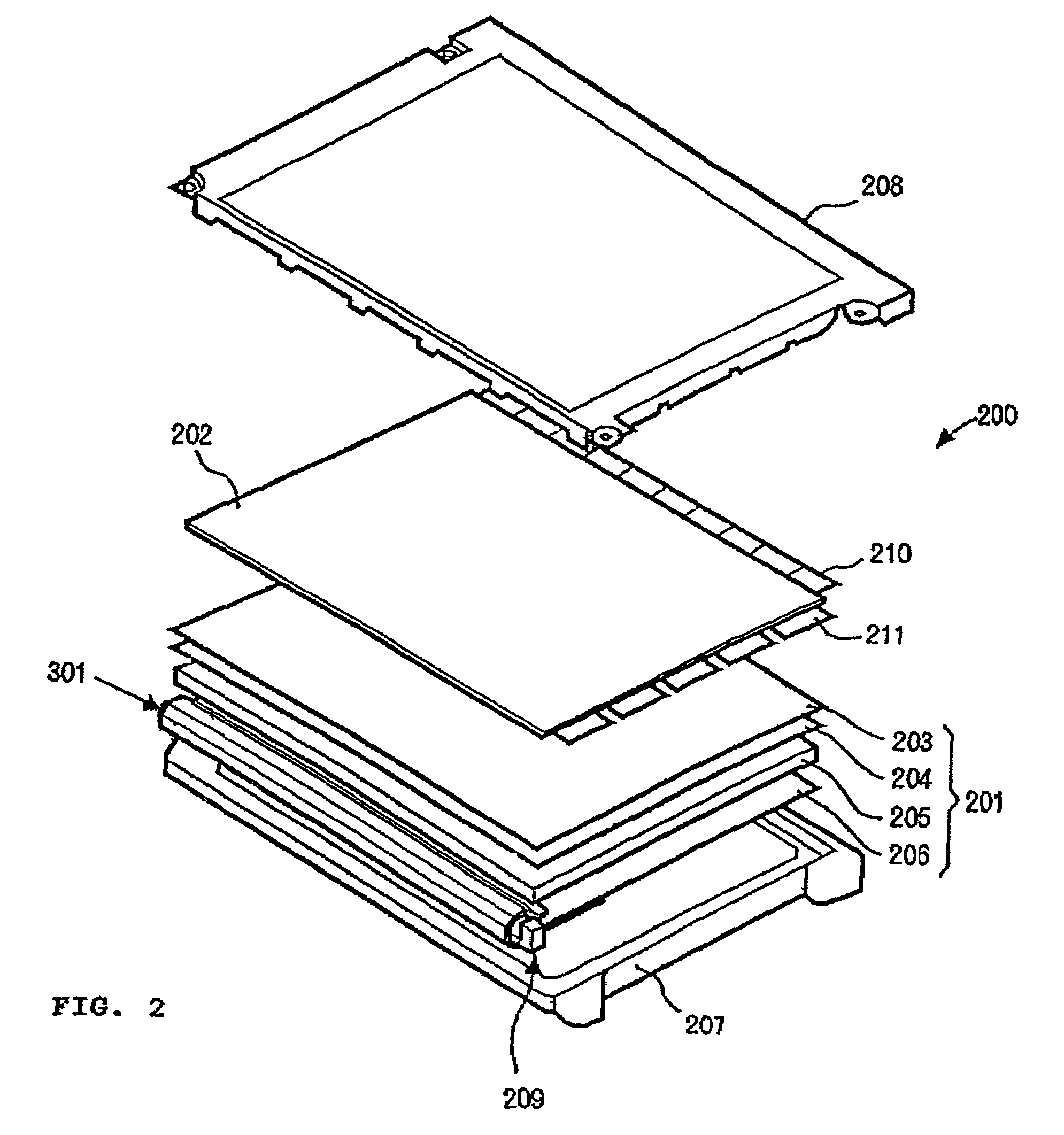
[0029]FIG. 2 is an exploded isometric view illustrating a liquid crystal display device according to one embodiment of the invention. FIG. 2 schematically shows the device 200 having a sidelight type backlight unit. In this drawing, reference numeral 201 denotes the backlight unit, and numeral 202 denotes a liquid crystal...


PUM

PropertyMeasurementUnit
heightaaaaaaaaaa
thicknessaaaaaaaaaa
thicknessaaaaaaaaaa

Abstract

A light source device and display device capable of suppressing occurrence of unevenness in luminance therefrom by using a light guide with concave or convex structural portions in combination with a reflection layer disposed adjacent the light guide and including a plurality of spacers for strategically positioning the layer's reflecting surface from the light guide. Light within the light guide is both reflected from the guide (e.g., to an adjacent display panel) or emitted onto the reflecting surface and passed back through the guide for eventual emission (e.g., to the same display panel). A reflection sheet including a base sheet, reflection layer and structural portions is also provided.

Description

BACKGROUND OF THE INVENTION[0001]The present invention relates to a planar light source device, a display device and an optical reflection sheet.[0002]As an image display device for a personal computer or other various monitors, use of liquid crystal display devices has been widespread. In general, a liquid crystal display device has a liquid crystal display panel and a backlight unit disposed on a back thereof. The liquid crystal display panel displays an image by controlling light transmitted therethrough. Among some types of liquid crystal display devices, there is one having a sidelight type backlight unit. The sidelight type backlight unit typically includes a cold cathode fluorescent tube as a light source disposed on a side of a display surface of the device.[0003]FIG. 1 is a side elevational view showing a liquid crystal display 10 having a sidelight type backlight unit. In this drawing, reference numeral 11 denotes a backlight unit. Numeral 12 denotes a liquid crystal displ...

Claims


Application Information

Patent Timeline
Patent Type & Authority Patents(United States)
IPC IPC(8): G09G3/36G02B6/00F21V8/00F21Y103/00G02B5/00G02B5/02G02B5/08G02F1/13357
CPCG02B6/0086G02B6/0055G02B6/0038G02B6/0046
Inventor KATSU, YOSHIHIRONISHIKAI, AKIKONOGUCHI, MICHIKAZUSUZUKI, MASARU
Owner TWITTER INC
Why Eureka
Try Eureka