Backlight unit and display device including the same

Inactive Publication Date: 2011-04-28
SHARP KK
View PDF8 Cites 31 Cited by
  • Summary
  • Abstract
  • Description
  • Claims
  • Application Information

AI Technical Summary

Benefits of technology

[0023]In this case, the light diffusing member is preferred to have a fixing portion fixed onto the surface of the substrate, and the opening portion of the second light reflective member is preferred to have a shape formed along a shape of the fixing portion of the light diffusing member. With this configuration, when fixing the light diffusing member onto the surface of the substrate, the opening portion of the second light reflective member serves as a mark to be used for placing the light diffusing member. Accordingly, the light diffusing member may be positioned with ease.
[0024]In the backlight unit according to the first aspect, the light emitting element comprises a plurality of light emitting elements and the light diffusing member comprises a plurality of light diffusing members. The plurality of light emitting elements are preferred to be arranged two-dimensionally and mounted on the surface of at least one of the substrate, and the plurality of light diffusing members respectively covering the plurality of light emitting elements are preferred to be provided on the surface of the at least one substrate. Further, one of the first light reflective member is preferred to have a plurality of the hole portion formed therein so that the surface of the at least one substrate is covered with the one first light reflective member. With this configuration, only one light reflective member is used, and hence the assembly man hours and assembly cost may be reduced.
[0025]In the backlight unit according to the first aspect, the light diffusing member is preferred to include an

Problems solved by technology

However, when the cold cathode fluorescent lamp is employed as the light source for the backlight unit, there has been suffered inconvenience as follows.
That is, the cold cathode fluorescent lamp fails to attain a sufficient light-emitting luminance and life.
In particular, the luminance on a low-pressure side is lowered, which makes it difficu

Method used


Image

  • Backlight unit and display device including the same
  • Backlight unit and display device including the same
  • Backlight unit and display device including the same

Examples


Embodiment Construction

[0039]First, with reference to FIGS. 1 to 5, a configuration of a display device according to an embodiment of the present invention is described in detail.

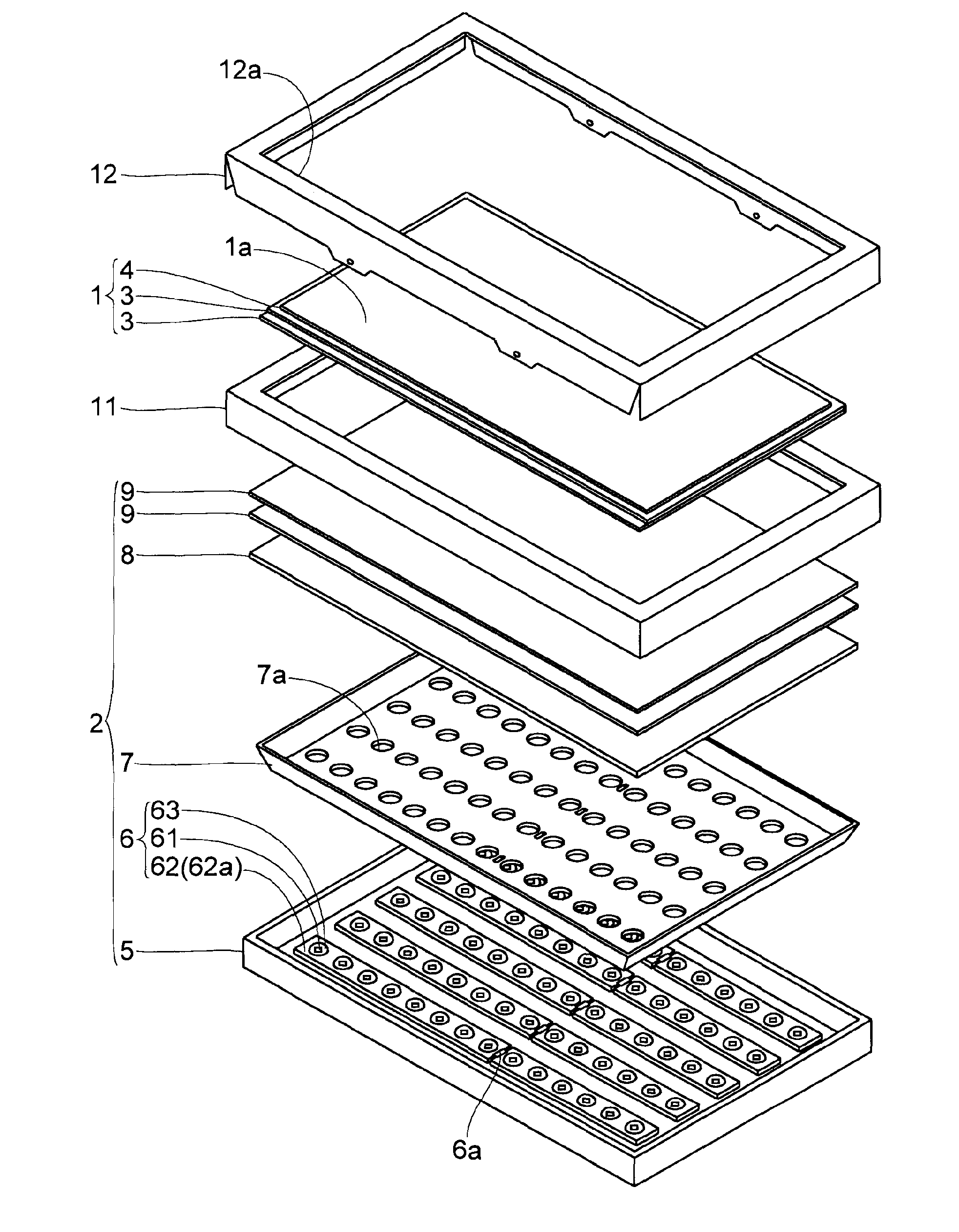
[0040]The display device is a liquid crystal display device, and includes, as illustrated in FIG. 1, a liquid crystal display panel (display panel) 1 having a display surface 1a, and a backlight unit 2 of direct light type, which is installed on a rear surface (surface opposite to the display surface 1a) side of the liquid crystal display panel 1.

[0041]The liquid crystal display panel 1 includes at least a liquid crystal layer (not shown), a pair of glass substrates 3, and a polarizing plate 4. The pair of glass substrates 3 are attached to each other across a seal material (not shown), and have a liquid crystal layer sandwiched therebetween. The polarizing plate 4 is disposed on each surface opposite to the liquid crystal layer side, of the pair of glass substrates 3. It should be noted that FIG. 1 illustrates only the polarizin...


PUM


Abstract

Provided is a backlight unit capable of increasing luminance and of reducing unevenness in luminance. The backlight unit includes: a light diffusing member provided to cover a light emitting element mounted on a surface of a substrate; and a first light reflective member having a hole portion opened larger in size than an outer shape of the light diffusing member, the first light reflective member being provided on the surface of the substrate while having the light diffusing member protrude from the hole portion. In addition, a second light reflective member is further provided on the surface of the substrate, and the second light reflective member covers at least a part of a region corresponding to a gap left between the light diffusing member and the hole portion of the first light reflective member.

Description

[0001]The present application claims priority from Japanese Patent Application No. 2009-245132 filed on Oct. 26, 2009, the content of which is hereby incorporated by reference into this application.BACKGROUND OF THE INVENTION[0002]1. Field of the Invention[0003]The present invention relates to a backlight unit and a display device including the same.[0004]2. Description of the Related Art[0005]A liquid crystal display device, which is a kind of a display device, includes a liquid crystal display panel for displaying an image. The liquid crystal display panel does not emit light, and hence a backlight unit is installed on a rear surface side (side opposite to a display surface side of the liquid crystal display panel) of the liquid crystal display panel so that the liquid crystal display panel is illuminated by the backlight unit, to thereby enable display operation.[0006]As a light source to be used for the backlight unit, there is known a cold cathode fluorescent lamp formed of a f...

Claims


Application Information

Patent Timeline
IPC IPC(8): G02F1/13357
CPCG02F1/133603G02F2001/133607G02F1/133605G02F1/133607
Inventor MURAKOSHI, KENICHIHIRANO, YASUAKIOGATA, NOBUOSUMINOE, SHINJIHINENO, MITSURUSEKIGUCHI, YOSHIHISAOHATA, TAKAFUMIHIROTA, MAKOTO
Owner SHARP KK
Why Eureka
Try Eureka