
LED Lamp Illumination Projecting Structure

a projecting structure and led lamp technology, applied in the direction of point-like light sources, lighting and heating apparatuses, lighting device details, etc., can solve the problems of poor directionality of light in led lamps and uneven brightness in the projecting area, and achieve good directionality of light

Inactive Publication Date: 2008-01-24
LEADER KEY +1
View PDF8 Cites 35 Cited by
  • Summary
  • Abstract
  • Description
  • Claims
  • Application Information

AI Technical Summary

Benefits of technology

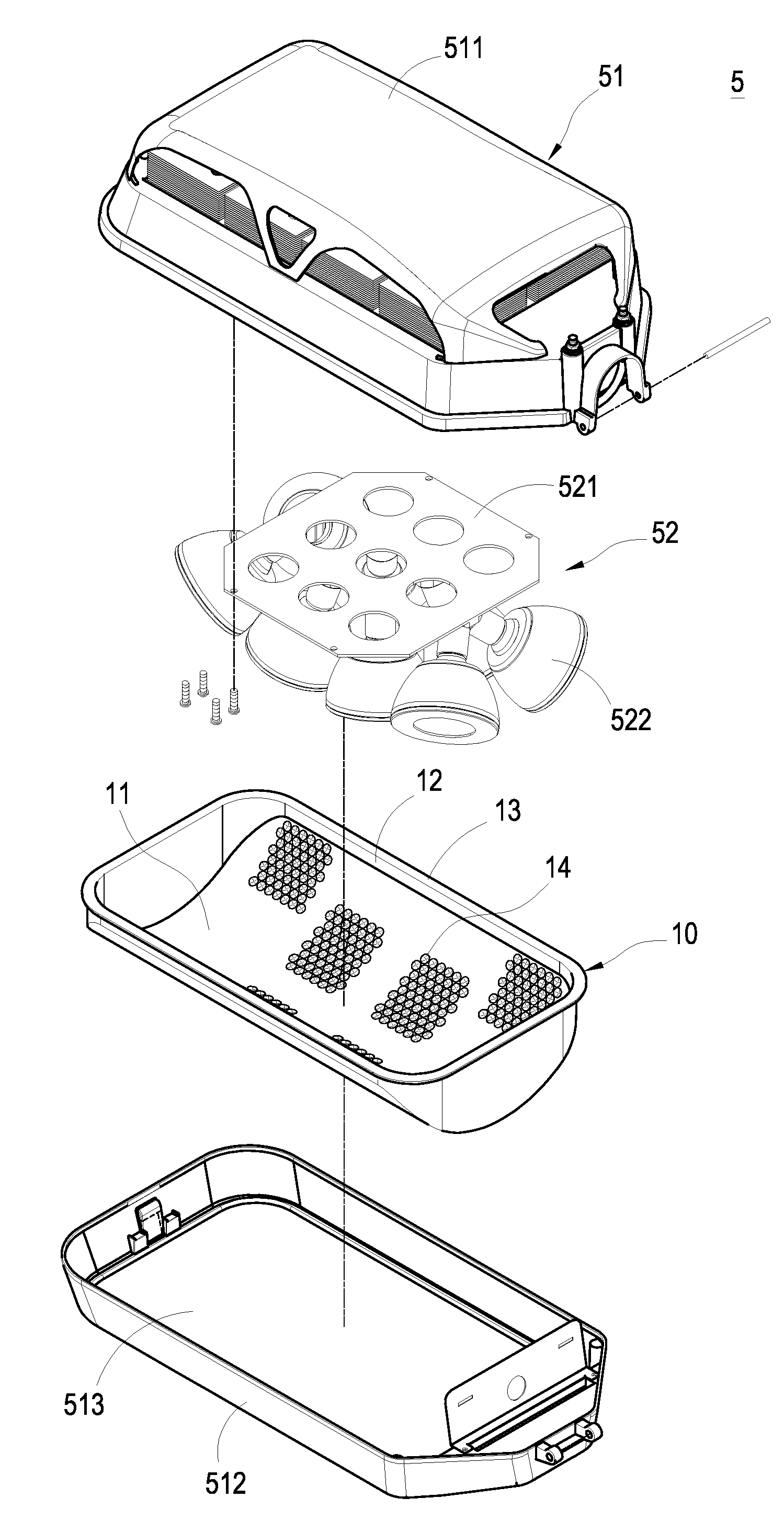
"The present invention is an LED lamp illumination projecting structure that solves the shortcomings of the prior art. It includes a pit on the internal surface of the light transmitting lens that corresponds to each LED lamp, allowing for better directionality of light and even brightness in the projecting area. The structure includes a casing, LED lamp set, and light transmitting lens. The LED lamps are connected to a base board, and the light transmitting lens is sealed onto the casing. The pits are formed on the internal side of the light transmitting lens and positioned to emit the light of each LED lamp. This design provides a more precise and effective illumination."

Problems solved by technology

Since the light transmitting lens does not come with the pits corresponding to the projecting position of each LED lamp, the LED lamp has a poor directionality of light and an uneven brightness in the projecting area.

Method used


Image

  • LED Lamp Illumination Projecting Structure
  • LED Lamp Illumination Projecting Structure
  • LED Lamp Illumination Projecting Structure

Examples


Embodiment Construction

[0015]The technical characteristics, features and advantages of the present invention will become apparent in the following detailed description of the preferred embodiments with reference to the accompanying drawings. However, the drawings are provided for reference and illustration only and are not intended for limiting the scope of the invention.

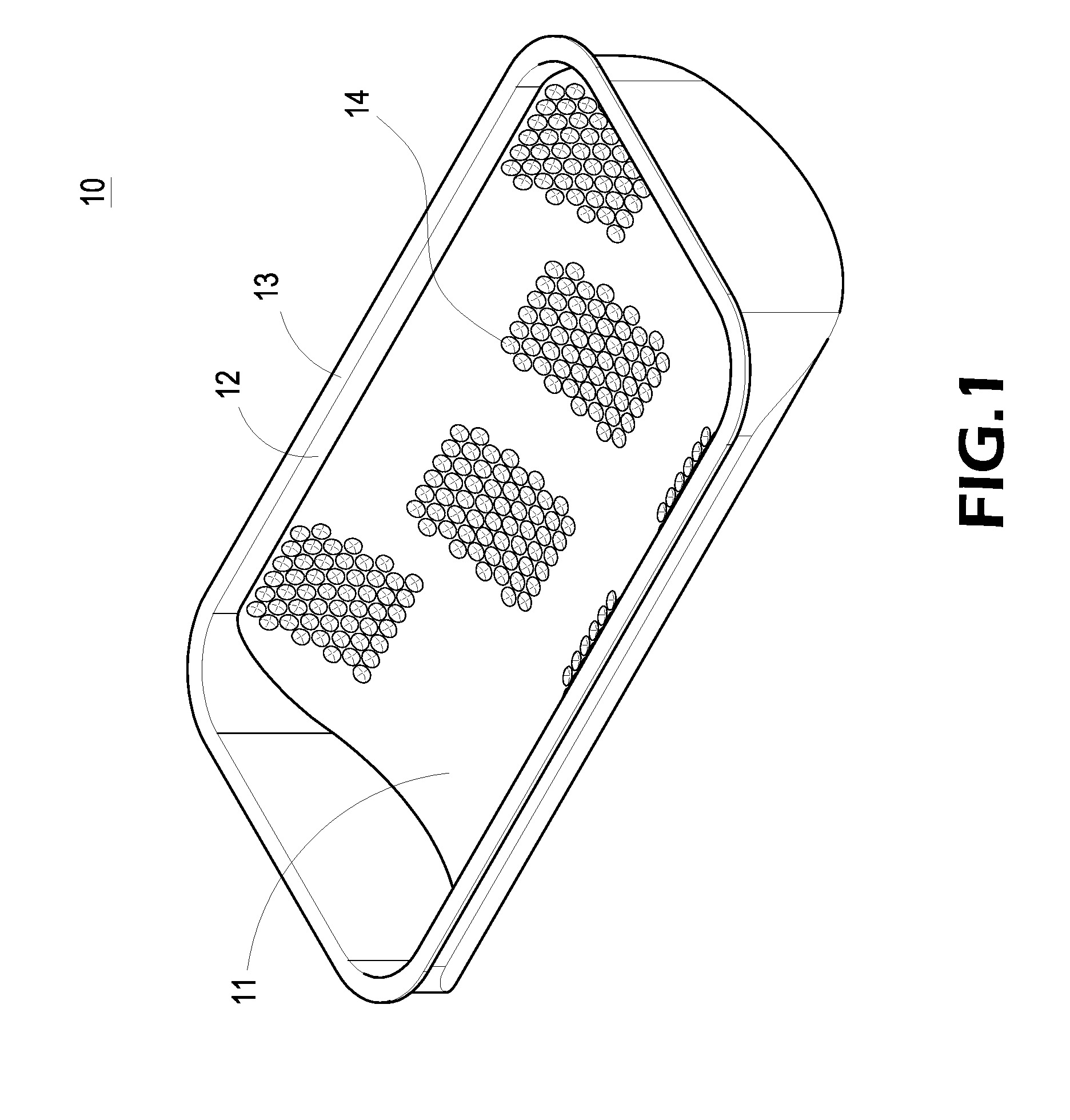
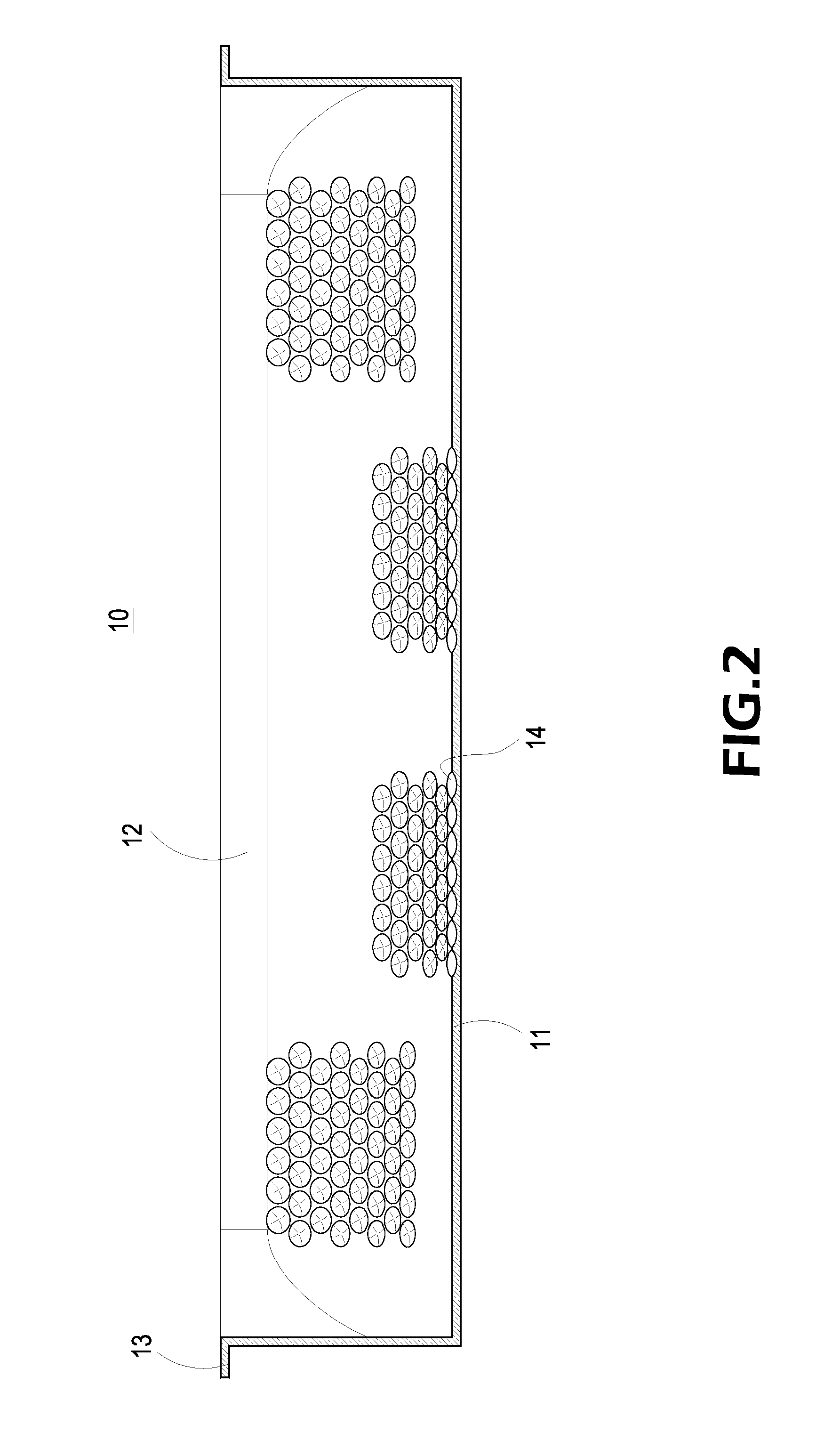
[0016]Referring to FIGS. 1 and 2 for the perspective view and cross-sectional view of a light transmitting lens in accordance with the present invention, an LED lamp illumination projecting structure is provided. The light transmitting lens 10 is made of a transparent material or a semi-transparent material, and the light transmitting lens 10 is comprised of a rectangular arc bottom panel 11, a surrounding panel 12 extended vertically upward from the periphery of the bottom panel 11, a flange 13 extended horizontally from the periphery of the top of the surrounding panel 12, and a plurality of concavely downward hemispherical pits 14 disp...


PUM


Abstract

In an LED lamp illumination projecting structure, an LED lamp includes a casing, an LED lamp set and a light transmitting lens. The casing has an LED lamp set with a base board mounted in the casing and several LED lamp connected to the base board, and the light transmitting lens is installed in the light projecting direction of the LED lamp set and sealed onto a side of the casing, and several pits arranged with an interval apart and formed on the internal surface at a position corresponding to the projected position of each LED lamp for collecting and emitting the light of each LED lamp through the pit, so as to provide a better directionality of the light of the LED lamp and an evener brightness for a projecting area.

Description

BACKGROUND OF THE INVENTION[0001]1. Field of the Invention[0002]The present invention relates to an LED lamp illumination projecting structure, and more particularly to an LED lamp illumination projecting structure capable of improving the directionality of the light and providing an even brightness of the LED lamp.[0003]2. Description of Prior Art[0004]Since light emitting diodes (LEDs) feature the high brightness, power saving and long life expectancy advantages, they have been used extensively for the illumination of lamps. Several LED lamps are usually connected to form an LED lamp set, and the position of each lamp can be adjusted to achieve an illumination effect to meet the requirements for a large projecting area and a high brightness. These LED lamp sets are used as illuminating devices indoors and outdoors. However, it is necessary to plan the LED lamps and the layout of different projecting areas, so as to differentiate the projecting area for each LED lamp with a differe...

Claims


Application Information

Patent Timeline
Patent Type & Authority Applications(United States)
IPC IPC(8): F21V5/04
CPCF21V5/00F21Y2101/02F21W2131/10F21V5/04F21Y2115/10
Inventor WANG, CHIN-WEN
Owner LEADER KEY
Learn More