Air dielectric cylindrical lens antenna

A technology of air medium and cylindrical lens, applied in the direction of antenna, electrical components, etc., can solve the problem of satellite load burden, achieve good directionality, reduce weight, and achieve simple effects

Inactive Publication Date: 2011-06-29
ZHEJIANG UNIV
View PDF0 Cites 22 Cited by
  • Summary
  • Abstract
  • Description
  • Claims
  • Application Information

AI Technical Summary

Problems solved by technology

In actual Ka-band satellite communication, in order to achieve a gain of 35dB, if a traditional dielectric material (such as Rexolite material, whose specific gravity is very close to water) is used, after calculation, in order to realize a multi-beam scanning antenna, the lens material required for light The weight needs to be 50-60 kg, which is a very heavy burden on the load of the satellite

Method used


Image

  • Air dielectric cylindrical lens antenna
  • Air dielectric cylindrical lens antenna
  • Air dielectric cylindrical lens antenna

Examples


Embodiment Construction

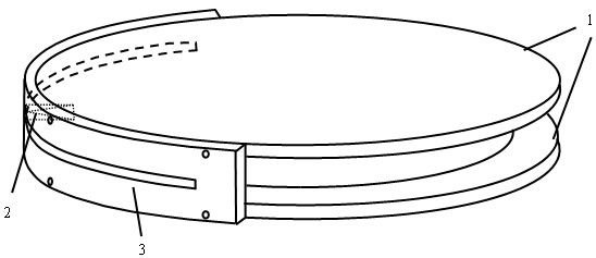
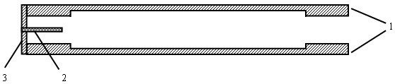
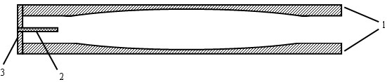
[0022] When the height of the parallel plate waveguide is chosen as / 2 when (of which, is the wavelength in free space), and the TE can be excited between the parallel plates 10 mode, so the antenna polarization direction is horizontal polarization. Using this principle, we can realize a lens antenna without any dielectric material. At the same operating frequency, different parallel plate waveguide heights will result in different propagation wave numbers. We control the relative refractive index of the air dielectric lens by selecting different parallel plate waveguide heights. At the same time, in order to achieve the optimal antenna aperture efficiency , the feed should be placed at its focal point. The direction pattern of this air dielectric cylindrical lens is similar to that of traditional cylindrical lenses. It can achieve narrow beams in the E plane (horizontal plane), and a very wide beam in the H plane (elevation plane). At the same time, due to the symmetry ...


PUM


Abstract

The invention discloses an air dielectric cylindrical lens antenna. The air dielectric cylindrical lens antenna comprises a metal disc-shaped parallel plate waveguide, a feed source antenna and arc-shaped metal support plates, wherein the metal disc-shaped parallel plate waveguide comprises an upper metal disc and a lower metal disc, the upper and the lower inner surfaces of the metal disc-shaped parallel plate waveguide are planes or arc-shaped surfaces, a central cavity of the metal disc-shaped parallel plate waveguide forms an air dielectric cylindrical lens, an annular boss is arranged below the edge of the upper disc of the metal disc-shaped parallel plate waveguide, the annular boss is arranged above the edge of the lower disc of the metal disc-shaped parallel plate waveguide, the feed source antenna is arranged between the two annular bosses, the feed source antenna is embedded in an arc-shaped groove between the arc-shaped metal support plates on the edges of the two metal discs, and the arc-shaped metal support plates are connected with the two metal discs through screws. The feed source antenna is a horizontal polarization gradient groove antenna or a horizontal polarization gradient groove antenna array.

Description

technical field [0001] The invention relates to an antenna, in particular to an air dielectric cylindrical lens antenna, which is especially suitable for millimeter wave band applications. Background technique [0002] A series of researches on lens antenna systems have been carried out in the world very early. Traditional lens antennas generally adopt geometric shapes such as planes, spheres, hyperboloids, and parabolas. However, these methods have limited scanning range, large losses, and narrow operating frequency bands, which cannot satisfy requirements of modern mmWave system applications. The research group led by Prof. G. M. Rebeiz of the University of Michigan proposed a dielectric lens antenna especially suitable for working in the millimeter wave band in 1993. The biggest feature of this antenna is that it can eliminate the surface wave loss of the millimeter wave antenna. In 1997, further , it is proposed that such an antenna can be used to generate multibeam sca...

Claims


Application Information

Patent Timeline
Patent Type & Authority Applications(China)
IPC IPC(8): H01Q19/06
Inventor 吴锡东华昌洲周建华杨楠朱道虹周金芳楚恒林杨龙
Owner ZHEJIANG UNIV
Why Eureka
Try Eureka