Projection type video display apparatus

Active Publication Date: 2006-04-20
SANYO ELECTRIC CO LTD
View PDF3 Cites 53 Cited by
  • Summary
  • Abstract
  • Description
  • Claims
  • Application Information

AI Technical Summary

Benefits of technology

[0005] With the above-described configuration, the cooling liquid draws heat generated by the light source by passing through the heat conductive portion. The cooling liquid of which temperature has risen by drawing the heat is guided to the radiation portion, and heat of the cooling liquid is radiated. The cooling liquid cooled by this heat radiation is returned to the pipe again and reaches the heat conductive portion. Thus, a circulation path is formed such that the cooling liquid circulates through from the heat conductive portion to the radiation portion, and then, to the heat conductive portion. Unlike a cooling by a fan, cooling capacity is not affected by an arrangement of optical parts in the apparatus. Furthermore, the cooling liquid is circulated as described above, so that cooled cooling liquid is always supplied to the heat conductive portion. As a result, a decrease in cooling capacity is prevented.
[0006] In such a projection type video display apparatus of the above-described configuration, it is preferable that the radiation portion is provided in an outside area partitioned off from an arrangement space of the light source. With such the configuration, the cooling liquid of which

Problems solved by technology

However, in the above-described prior art, air flow generated by the fan is exhausted by passing through various optical parts in the apparatus, so that there may be a case where the light source, and the like, cannot be sufficiently cooled depending on how

Method used


Image

  • Projection type video display apparatus
  • Projection type video display apparatus
  • Projection type video display apparatus

Examples


Example

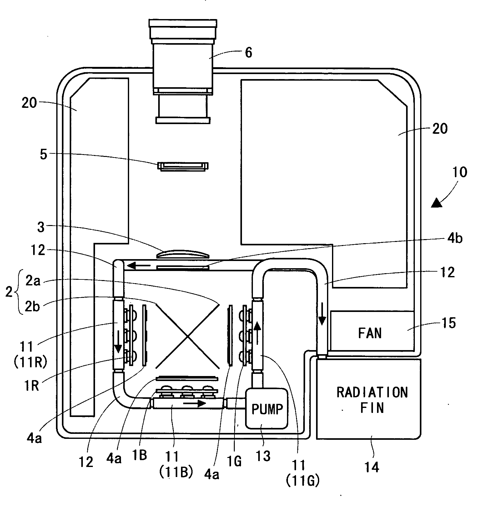
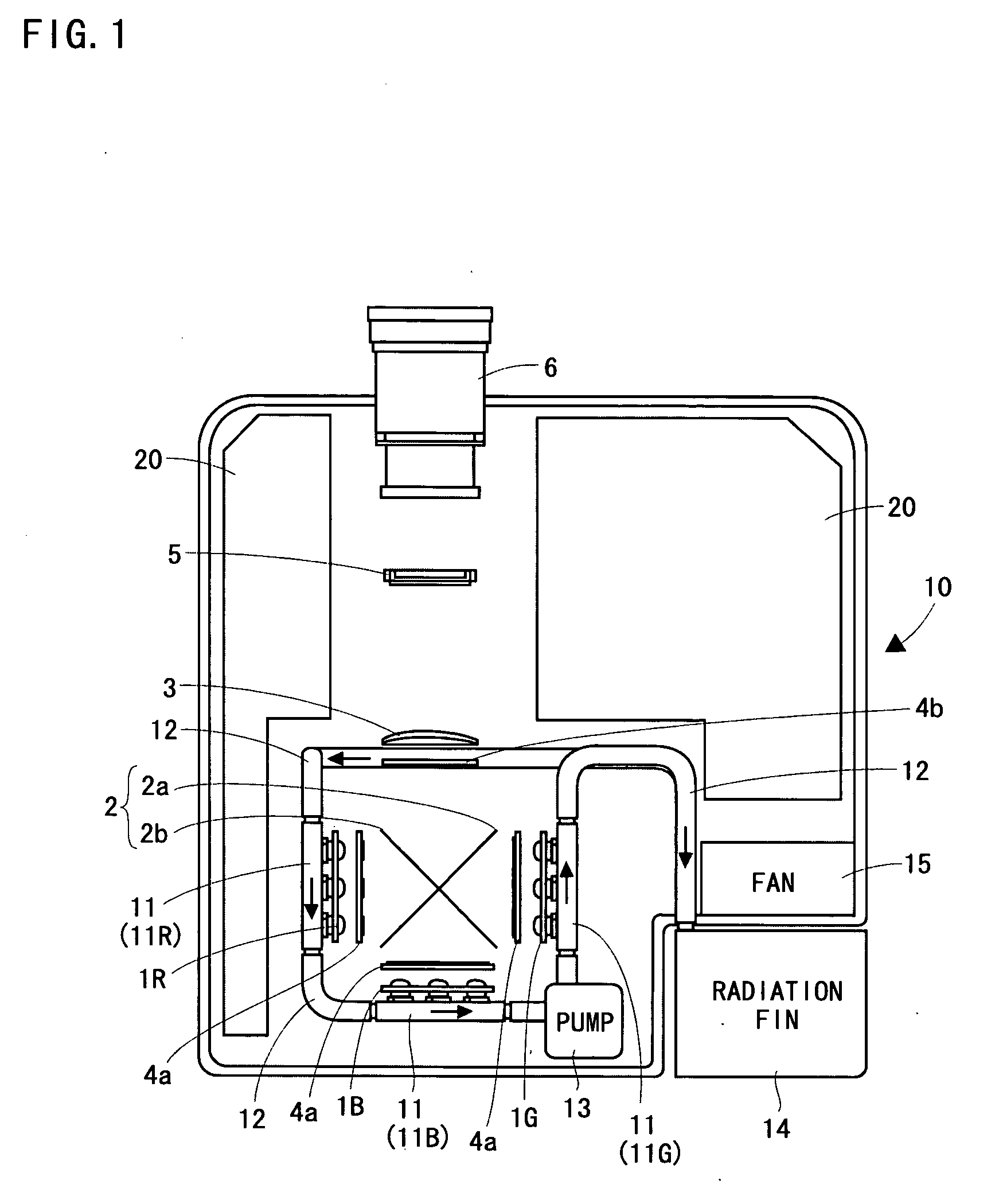
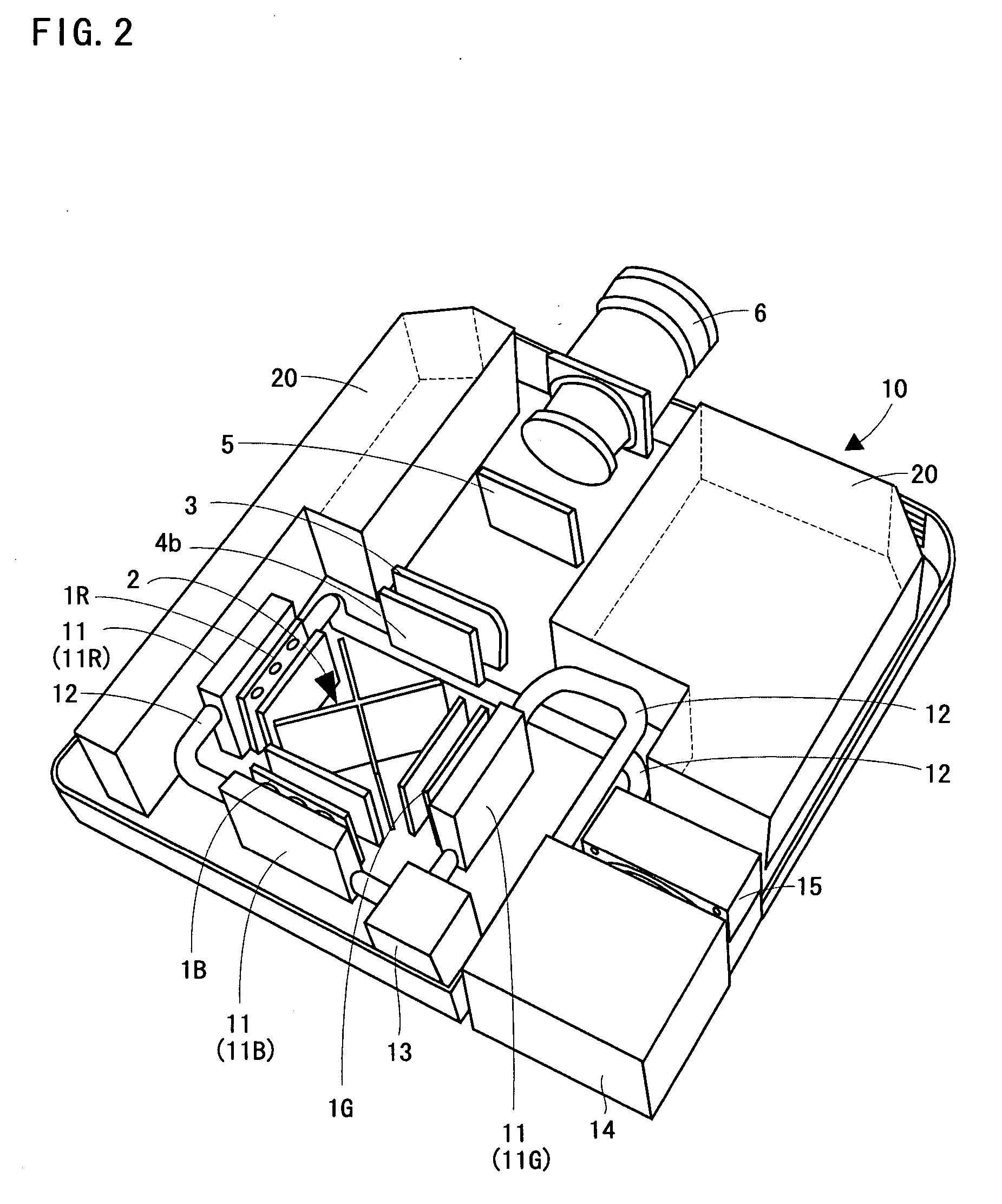
[0041] (First embodiment) Hereinafter, a projection type video display apparatus according to a first embodiment of the present invention will be described with reference to FIG. 1 and FIG. 2.

[0042]FIG. 1 is a plan view showing a single-panel projection type video display apparatus 10, and FIG. 2 is a perspective view of the projection type video display apparatus 10. The projection type video display apparatus 10 is provided with LED light sources 1R, 1G, 1B as three light sources (hereinafter, numeral “1” is used for generally referring to the LED light source). Each LED light source 1 has structure in which LEDs (Light-emitting diodes) are arranged in an array shape. The LED light source 1R emits light in red, the LED light source 1G emits light in green, and the LED light source 1B emits light in blue.

[0043] The LED light source 1B is arranged in such a manner as to face a light-incidence surface of a lens 3 with sandwiching a cross dichroic mirror 2, and the LED light source ...

Example

[0057] (Second embodiment) The second embodiment of the present invention will be described with reference to FIG. 3. It is noted that the same numerals are added to the same members as those shown in FIG. 1, and descriptions thereof are omitted. A cross dichroic mirror 2′ is provided with a first dichroic mirror portion 2a and a second cross dichroic mirror portion 2c in the cross arrangement. The first cross dichroic mirror portion 2a reflects light in red and transmits light in other colors. The second cross dichroic mirror portion 2c reflects light in blue and transmits light in other colors. In this embodiment, degrees of deterioration by heat in a plurality of LED light sources 1 (degradation in display performance such as luminance degradation, wavelength shift, a chromaticity change caused by a change of half bandwidth, etc.) are different one another, and the degree of deterioration by heat in the LED light source 1R for emitting light in red is the greatest. The cooling li...

Example

[0059] (Third embodiment) The third embodiment of the present invention will be described with reference to FIG. 4. It is noted that the same numerals are added to the same members as those shown in FIG. 1, and descriptions thereof are omitted. In the configuration shown in FIG. 1, the cooling liquid which passes through the heat conductive portion 11G for the LED light source 1G is to be guided to the radiation fin 14. On the other hand, in the configuration shown in FIG. 4, the cooling liquid which passes through the heat conductive portion 11G for the LED light source 1G is, via a heat conductive portion 22 for power source, guided to the radiation fin 14. The heat conductive portion 22 for power source is provided to draw heat generated by a power source 21 arranged in a circuit portion 20. Such the configuration makes it possible to exhaust also the heat generated by the power source 21 outside the case and to restrain the temperature rise in the case. Furthermore, it is possib...


PUM


Abstract

There is provided a heat conductive portion for conducting heat generated by an LED light source to cooling liquid at a rear side of each LED light source. Each heat conductive portion is connected one another with a pipe, and the cooling liquid flowing in the pipe is sequentially circulated through each heat conductive portion. A heat generation amount of an LED light source for red light is the smallest, the heat generation amount of an LED light source for green light is the largest, and the heat generation amount of an LED light source for blue light is the middle of the two. The cooling liquid cooled by passing through a radiation fin is firstly supplied to the heat conductive portion for the LED light source for red light, secondly supplied to the heat conductive portion for the LED light source for blue light, and lastly supplied to the heat conductive portion for the LED light source for green light. The cooling liquid discharged from a pump is supplied to the heat conductive portion for the heat conductive portion for the LED light source for green light. Then, the cooling liquid from this heat conductive portion passes through the pipe to be supplied to the radiation fin (radiator).

Description

BACKGROUND OF THE INVENTION Field of the Invention [0001] The present invention relates to a projection type video display apparatus such as a liquid crystal projector, and the like. Because of a configuration in which light emitted from a light source is modulated by a light valve such as a liquid crystal panel, etc., and the modulated light is projected, a projection type video display apparatus needs to be provided with a high-intensity light source. For this, it is needed to prepare measures against heat generated from the high-intensity light source. Conventionally, the light source is cooled by blowing cooling air generated by a fan to the light source, and air in the apparatus, of which temperature has risen, is exhausted outside the apparatus (Japanese Patent Laying-open No. 2001-222065). SUMMARY OF THE INVENTION [0002] However, in the above-described prior art, air flow generated by the fan is exhausted by passing through various optical parts in the apparatus, so that ther...

Claims


Application Information

Patent Timeline
IPC IPC(8): G02F1/1335G03B21/00
CPCH04N9/3141H04N9/3144H04N9/3197
Inventor MIWA, TAKASHIIKEDA, TAKASHI
Owner SANYO ELECTRIC CO LTD
Why Eureka
Try Eureka