

Cooling capacity measurement method for inverter device
- Summary
- Abstract
- Description
- Claims
- Application Information
AI Technical Summary
Benefits of technology
Problems solved by technology
Method used
Image

Examples
first embodiment
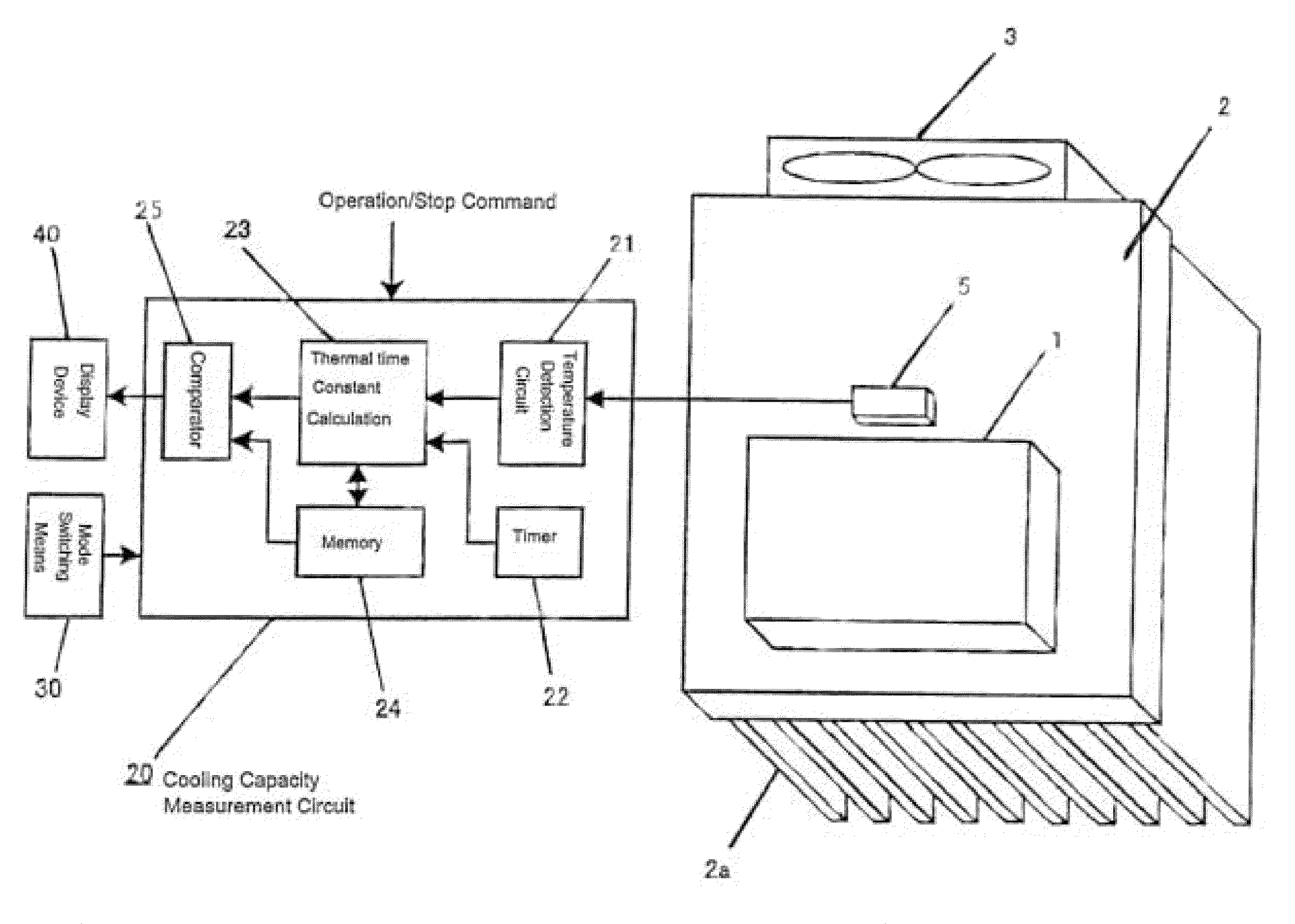
[0023]FIG. 1 is a structural diagram illustrating the present invention. A heat-generating component 1, such as a diode and an IGBT that is a structural component of an alternating current-direct current conversion unit and a direct current-alternating current conversion unit, is provided on a cooling fin 2. The cooling fin 2 is provided with a large number of fin portions 2a. A cooling fan 3 cools the cooling fin 2. A temperature sensor 5 detects the temperature of the cooling fin 2 and is disposed on the cooling fin 2 in the vicinity of the heat-generating component 1.
[0024]A cooling capacity measurement circuit 20 is provided that includes a temperature detection circuit 21, a timer 22, a thermal time constant calculation circuit 23, a memory 24, and a comparator 25. The cooling capacity measurement circuit serves to determine a decrease in cooling capacity on the basis of a variation amount in a temperature detection value. The temperature detection circuit 21 outputs the temper...
second embodiment
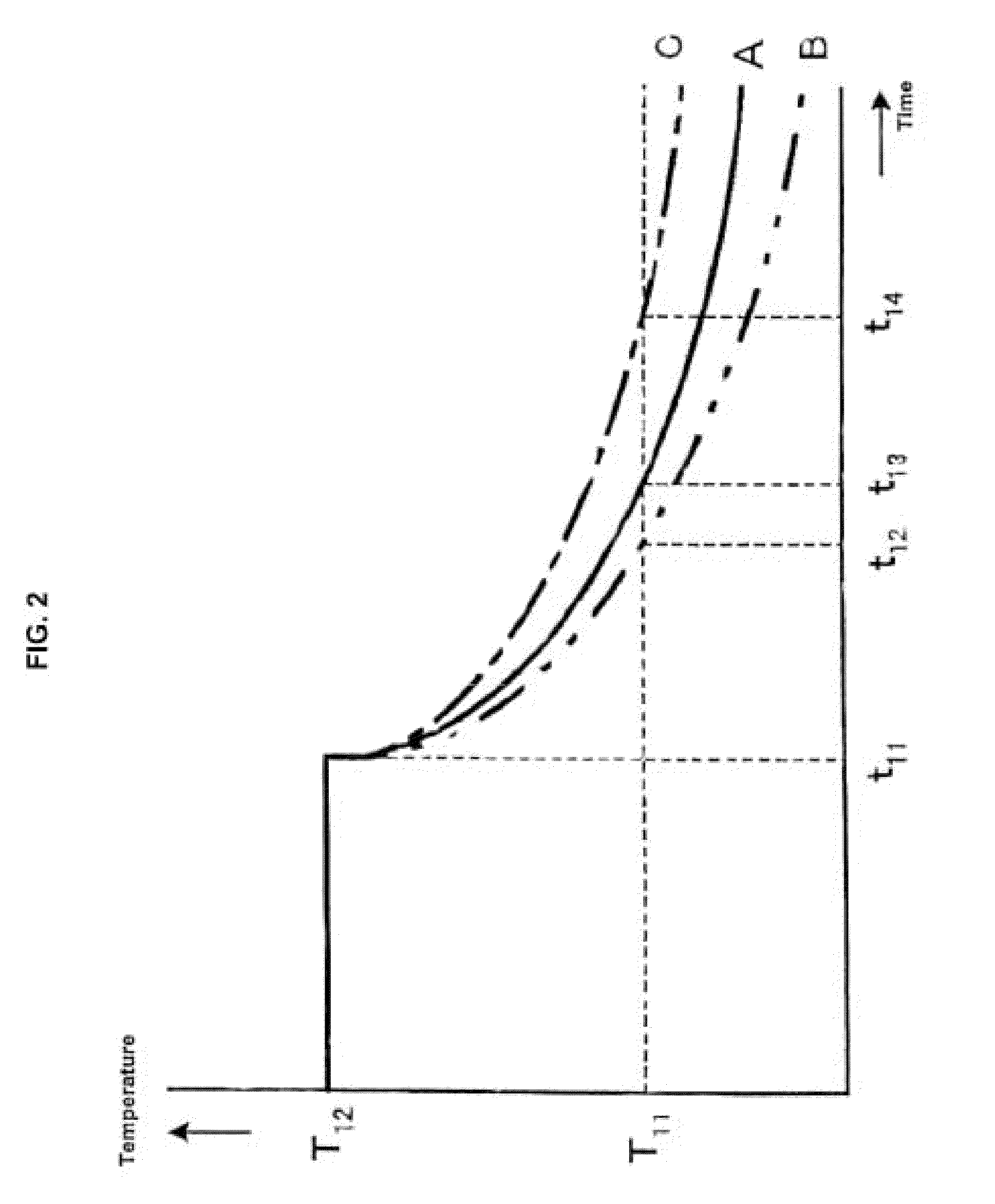
[0032]FIG. 3 is a characteristic diagram of temperature variations at the time the inverter device operation is started. A method for measuring the cooling capacity of the cooling fan of the second embodiment will be explained below with reference to FIG. 1 and FIG. 3. In FIG. 3 a characteristic D serves as a reference value of the thermal time constant that has been set in advance and illustrates a case in which an interval from the time t21 to the time t23 is required for the temperature detection value T21, which is detected at the point in time t21 at which the inverter device starts operating, to change to T22 (temperature variation amount ΔTC2). A characteristic E relates to normal cooling capacity and illustrates a case in which an interval from the time t21 to the time t24 is required for the temperature detection value T21, which is detected at the point in time at which the inverter device starts operating, to change to T22 (temperature variation amount ΔTC2). A characteri...
third embodiment
[0038]FIG. 4 is a circuit diagram illustrating the present invention. In FIG. 4, an alternating current power source 11 supplies power to a load such as a motor 12. An alternating current-direct current conversion unit 13 that converts an alternating current input into a direct current. A smoothing capacitor 14 is provided that smoothes the output of the alternating current-direct current conversion unit 13. A direct current-alternating current conversion unit 15 converts a direct current input into an alternating current. A voltage detector 16 detects voltage between both terminals of the smoothing capacitor 14. A current detector 17 detects an output current of the inverter device.
[0039]Similar to the configuration shown in FIG. 1, a heat-generating component 1 such as a diode or an IGBT (see FIG. 1) that is a constituent component of the alternating current-direct current conversion unit 13 and direct current-alternating current conversion unit 15 is carried on a cooling fin 2 (s...
PUM
 Abstract
Description
Claims
Application Information