Drying machine

a drying machine and drying liquid technology, applied in drying machines, lighting and heating apparatus, furnaces, etc., can solve the problems of increased energy costs, increased energy consumption, and long time required to dry the matter to be dried, so as to secure the recovery efficiency of the washing liquid in the evaporator, and effectively prevent a disadvantage

a drying machine and drying liquid technology, applied in drying machines, lighting and heating apparatus, furnaces, etc., can solve the problems of increased energy costs, increased energy consumption, and long time required to dry the matter to be dried, so as to secure the recovery efficiency of the washing liquid in the evaporator, and effectively prevent a disadvantage

US20060053651A1Inactive Publication Date: 2006-03-16SANYO ELECTRIC CO LTD +1

Image

  • Drying machine
  • Drying machine
  • Drying machine

Examples


Embodiment Construction

[0029] The present invention has been attained to solve conventional technical problems, and provides a drying machine which achieves delicate drying and which can reduce burdens on a matter to be dried during drying while ensuring a predetermined evaporation temperature in an evaporator. Embodiments of the present invention will hereinafter be described in detail with reference to the drawings.

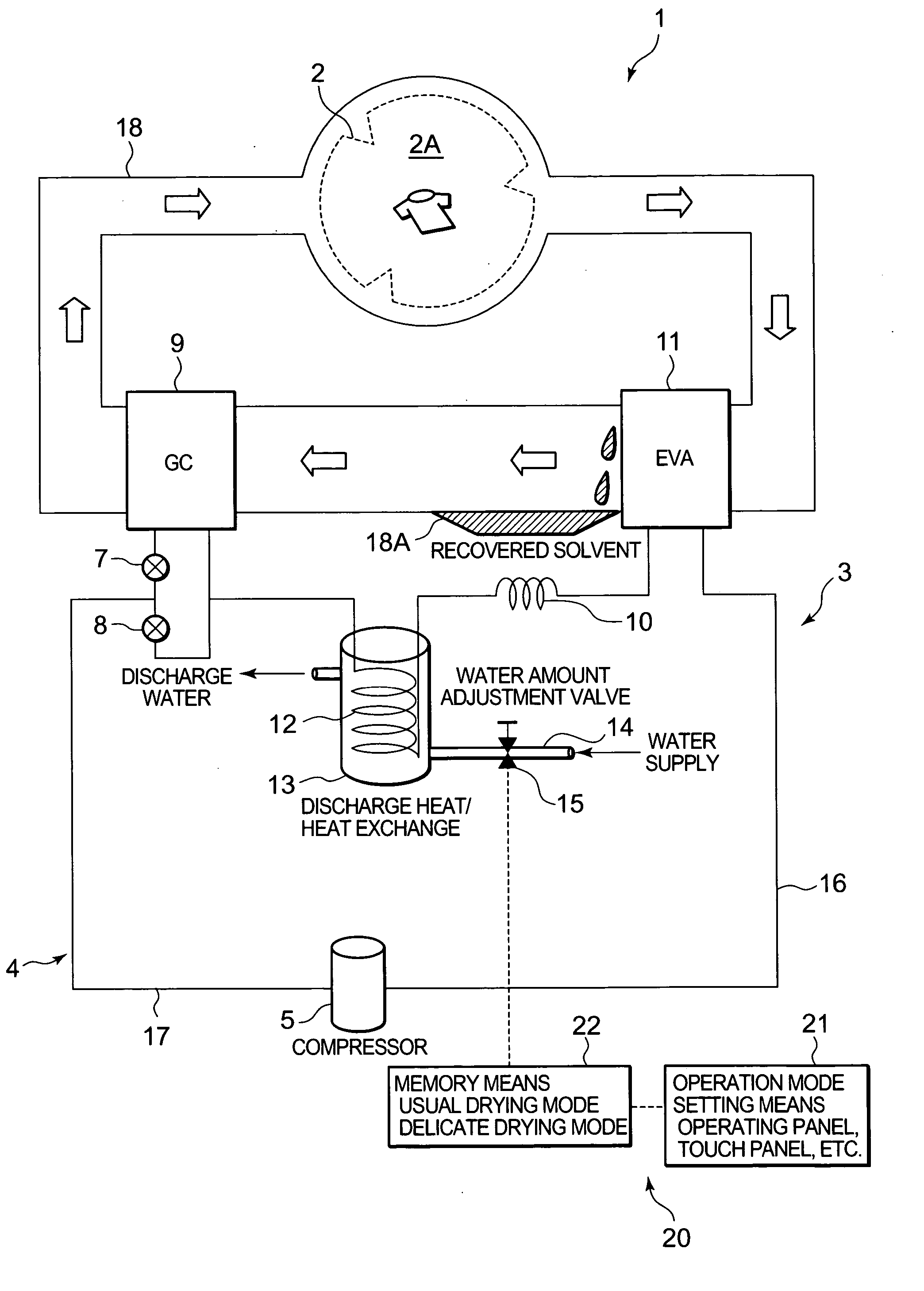
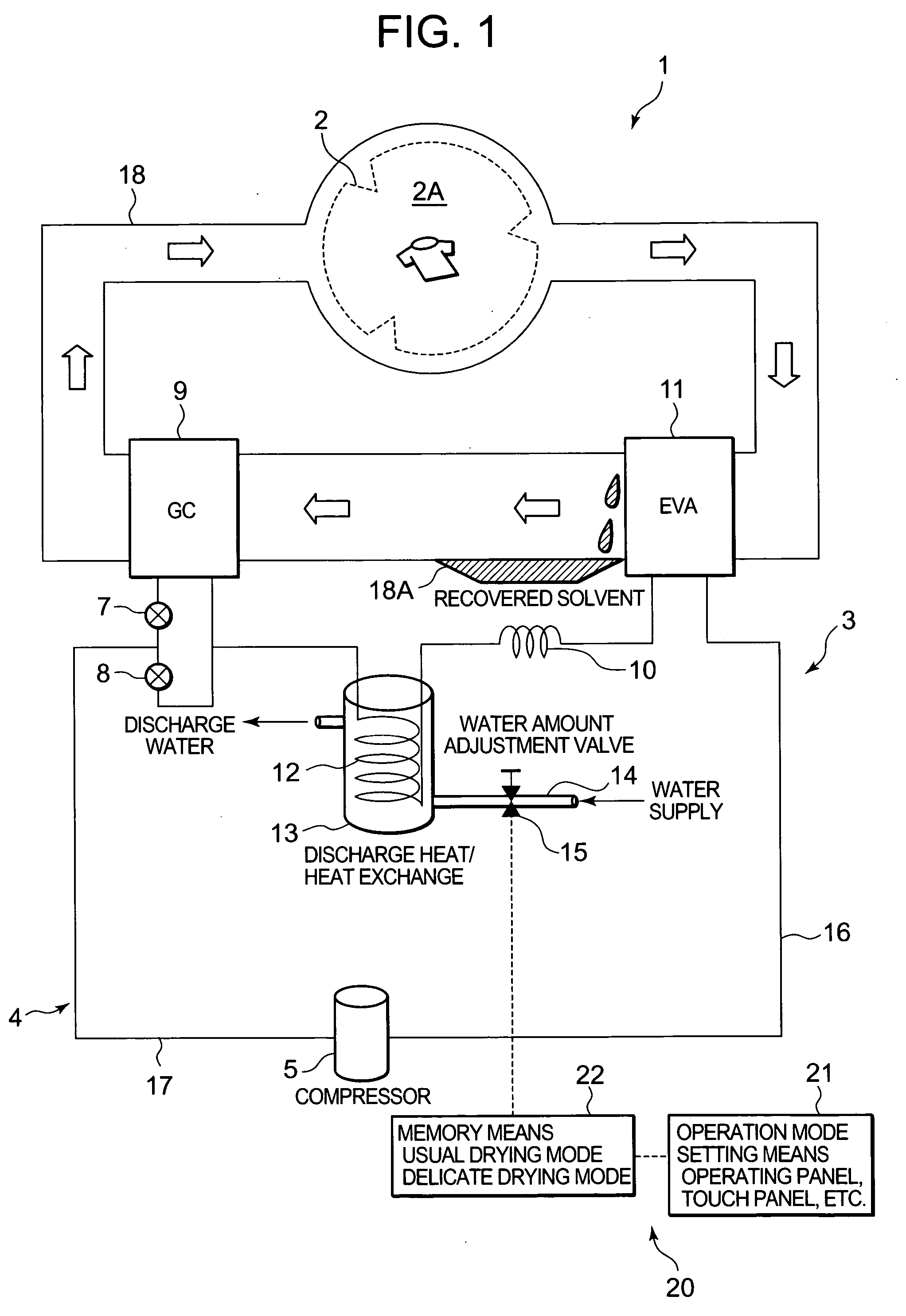
[0030]FIG. 1 shows a schematic constitution diagram of a dry cleaner 1 using, for example, a petroleum-based solvent as a cleaning fluid, in one embodiment of the drier to which the present invention is applied. In the drawing, 2 denotes a cylindrical drum including a large number of through holes formed in a peripheral wall, and clothing is washed with a washing liquid in a storage chamber 2A of the drum 2 and subsequent drying is also performed therein. This drum 2 is rotated by an unshown drum motor, for example, at a speed of 30 to 50 rpm.

[0031] Moreover, there is connected, to the drum...


PUM


Abstract

An object is to provide a drying machine which can accomplish delicate drying and reduce burdens on a matter to be dried during drying while securing a predetermined evaporation temperature in an evaporator. In summary, a dry cleaner equipped with a heat pump device comprises a water-cooling heat exchanger which removes heat from a refrigerant entering a capillary tube; and a control device which variably controls a discharged heat amount in the water-cooling heat exchanger and capacity of the compressor, wherein the control device has at least two kinds of drying modes including a usual drying mode and a delicate drying mode, and in the delicate drying mode, a temperature of air discharged into a storage chamber is set lower than in the usual drying mode to control the capacity of the compressor and to increase the discharged heat amount in the water-cooling heat exchanger.

Description

BACKGROUND OF THE INVENTION [0001] The present invention relates to a drying machine which comprises a storage chamber to store a matter to be dried and which executes a drying operation for the matter to be dried in the storage chamber. [0002] In such a drying machine, an electric heater or a gas burning heater has heretofore been used as a heat source. After heating outside air by the electric heater or the burning heater to produce high-temperature air, the air is blown into a storage chamber in which the matter to be dried is stored to thereby dry the matter to be dried in the storage chamber. Moreover, the high-temperature air in the storage chamber, which has dried the matter to be dried, is discharged to the outside. [0003] However, in the drying machine using such an electric heater or gas burning heater, as low-temperature humid air outside the storage chamber is used for the high-temperature air sent into the storage chamber, a long time is required until the matter to be ...

Claims


Application Information

Patent Timeline
16 Mar 2006
Publication
US20060053651A1
IPC
F26B21/06; F26B3/00
CPC
D06F58/206; D06F43/086
Inventors
TADANO, MASAYA; MASUDA, TETSUYA