Directional microphone assembly for mounting behind a surface

a microphone and surface technology, applied in the direction of electrical transducers, piezoelectric/electrostrictive transducers, transducer types, etc., can solve the problems of large pressure differences at the microphone elements, general overlooking or not fully addressed, etc., to achieve simple acoustic impedance to the opening, less sensitive, and larger pressure differences

Inactive Publication Date: 2006-09-19
ETYMOTIC RES
View PDF16 Cites 22 Cited by
  • Summary
  • Abstract
  • Description
  • Claims
  • Application Information

AI Technical Summary

Benefits of technology

[0017]The described structure is considerably less sensitive than the prior art to coupling degradations from the mounting surface for several reasons. First, the coupling from the element diaphragm to the surface opening is more direct, presenting a simpler acoustic impedance to the opening. Second, the impedance presented to each opening is identical. Assuming substantial similarity in the openings, some small degradation of frequency response and level might be experienced with, for example, a semi-transparent cloth covering, but potentially much larger response and pattern variations resulting from differing degradations of amplitude and phase response at each coupling is avoided. Third, assuming that well-controlled directionality is not required at very high frequencies, the microphone elements and their openings can be positioned farther apart than is practical with the prior art. The desired sound pickup can then result in larger pressure differences at the microphone elements in comparison to degradation-related differences than would otherwise occur. For a pickup pattern between cardioid and supercardioid, a preferred embodiment employs a spacing distance between the openings of, for example, 3.5 cm, allowing the maintenance of good directionality to past 3 kHz.
[0018]The present invention also includes several features to minimize the microphone assembly's sensitivity to the effects of amplitude and phase response mismatches between the elements. These effects have generally been overlooked or not fully addressed in prior art descriptions of differenced microphone arrays. The present invention employs the maximum practical inter-element spacing to maximize the desired acoustical signal differences while minimize any degradations which occur as a result of coupling or mismatches in the elements. Since the greatest mismatch-induced response and pattern errors appear in the lower frequencies where the desired acoustical signal differences are smallest, aberrant behavior from the resultant exaggerated low-frequency responses is minimized by the inclusion of a high-pass filter following the pattern-generating differencing operation. Such a filter clearly demarcates the lower end of the useful frequency range. This filter may also be conveniently used to shape the assembly's frequency response just above this lower end. Very low-frequency transient problems may also be minimized by the use of matching high-pass filters applied to the microphone element signals before significant signal amplification takes place. Finally, since the greatest source of inter-element phase mismatch results from differences in the low-frequency extension of the elements' low-frequency cutoffs, the phase mismatch error source can be minimized by employing microphone elements with well-controlled, very low, low-frequency cutoffs.

Problems solved by technology

The desired sound pickup can then result in larger pressure differences at the microphone elements in comparison to degradation-related differences than would otherwise occur.
These effects have generally been overlooked or not fully addressed in prior art descriptions of differenced microphone arrays.

Method used


Image

  • Directional microphone assembly for mounting behind a surface
  • Directional microphone assembly for mounting behind a surface
  • Directional microphone assembly for mounting behind a surface

Examples


Embodiment Construction

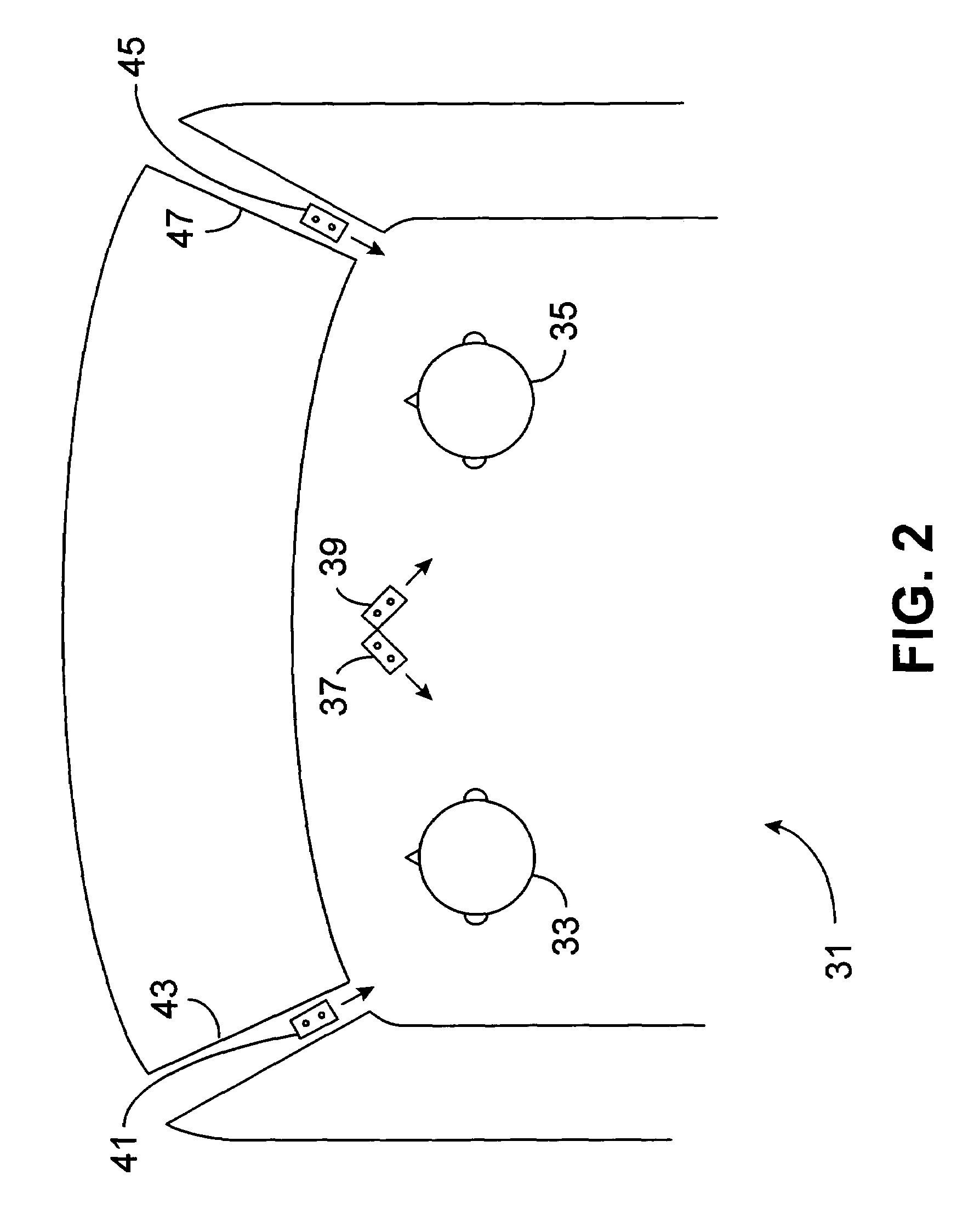
[0037]FIG. 2 illustrates a typical application for the present invention. A partial top view of a vehicle cabin 31 is shown with a left-hand driver 33 and a right-hand passenger 35. For right-hand drive vehicles, the driver and passenger positions are interchanged. A microphone assembly 37 of the present invention intended for speech pickup for hands-free telephony and other communication and control applications is shown mounted to and behind the cabin interior trim roof headliner or behind the surface of a headliner-mounted accessory console. For a telephony application, the assembly should generally provide a well-controlled directional pattern and frequency response over a frequency range of approximately 300 Hz to 3 kHz. For applications such as speech recognition and in-car speech reinforcement, useful response may need to extend to 5 kHz or beyond, but with some relaxation of directional pattern accuracy being acceptable. Within the constraint that the directional pattern mus...


PUM


Abstract

A directional microphone assembly suitable for subsurface mounting. A directional pickup pattern is developed from the outputs of a plurality of omnidirectional microphone elements mounted in an assembly behind a surface such that their acoustic excitation comes from the opposite side of the surface through small openings in the surface. The openings may have varying dimensions and may be covered with acoustically semi-transparent material without significantly degrading the assembly frequency response or polar pattern. Precautions are taken to ensure design robustness considering practical microphone element characteristics and potential high levels of low-frequency excitation.

Description

CROSS-REFERENCE TO RELATED APPLICATIONS[0001]Not applicableSTATEMENT REGARDING FEDERALLY SPONSORED RESEARCH OR DEVELOPMENT[0002]Not applicableBACKGROUND OF THE INVENTION[0003]The present invention relates to directional microphone assemblies, and particularly to those which may be used in applications which benefit from minimum visual intrusion. A primary example of these applications is use in vehicle cabins for speech pickup for hands-free telephony and other communication and control applications. Both omnidirectional and directional microphones have been used for this purpose. These are generally mounted on interior surfaces, most typically at a forward, central headliner position or near the top of the driver side roof-support pillar. Omnidirectional microphones have also been mounted behind such surfaces, with sound entering through a relatively small surface hole or group of holes or slots. This behind-the-surface mounting is aesthetically preferable to over-the-surface mount...

Claims


Application Information

Patent Timeline
Patent Type & Authority Patents(United States)
IPC IPC(8): H04R9/08H04R3/00H04R29/00
CPCH04R3/005H04R29/006H04R2499/13H04R25/407
Inventor JULSTROM, STEPHEN D.SCHULEIN, ROBERT B.
Owner ETYMOTIC RES
Why Eureka
Try Eureka