
Suspension for a pressure sensitive touch display or panel

a touch display or touch panel technology, applied in the direction of electrical apparatus casings/cabinets/drawers, instruments, wireless commuication services, etc., can solve the problems of reducing clarity, dead spots, and poor production yield, and achieve cost-effective effects

Active Publication Date: 2011-03-03
APPLE INC
View PDF16 Cites 97 Cited by
  • Summary
  • Abstract
  • Description
  • Claims
  • Application Information

AI Technical Summary

Benefits of technology

[0018]It is, therefore, an object of the present innovation to allow for cost efficient design and manufacturing of force sensing sensor-based touch screen products of different sizes, designs, and applications with one and the same conceptual component.
[0019]It is another object to provide a suspension solution that can be implemented and assembled at a low cost, and yet support different sensor types and sizes without any conceptual changes and a minimum of component changes.
[0021]It is another object to provide a suspension solution that is less sensitive for external interference, such as vibrations.

Problems solved by technology

The disadvantage of a resistive pad is that the resistive membrane material will wear out, initially resulting in further reduced clarity followed by dead spots.
In addition, the production yield is typically rather poor, and the technology has a few disadvantages such as a fixed (non-user adjustable) actuation force and the light throughput through the resistive membranes is typically only around 70% to 75%.
Capacitive pads are relatively expensive to manufacture compared to resistive pads, and can only detect objects with sufficient capacitance.
Small objects, such as the end of a regular stylus or pen, do not have enough capacitance to ground or transcapacitance to be detected by a capacitive touchpad.
This often leads to difficulties in implementing certain end-user features, such as handwriting recognition.
These devices work well, but are generally much too expensive for general applications.
Infra red light based displays work in a similar fashion, but this technology typically adds a large size and price.
The market success for force based touch screens and pads has so far been very limited for various reasons.
However, the assembly process is not optimal.
In addition, it is difficult to apply a dust or water seal which typically requires a rubber or silicon material to touch the touch lens, and the seal must typically also be tailor made as well as tested and verified for each new design.

Method used


Image

  • Suspension for a pressure sensitive touch display or panel
  • Suspension for a pressure sensitive touch display or panel
  • Suspension for a pressure sensitive touch display or panel

Examples


Embodiment Construction

[0030]The present invention is a suspension platform for a touch sensitive input panel or display having a touch surface, which is especially suited for use in cellular phones, personal digital assistants (PDAs), and PC Tablets, as well as laptops, PCs, office equipment, medical equipment, TV Monitors, or any other device that uses touch sensitive displays or panels.

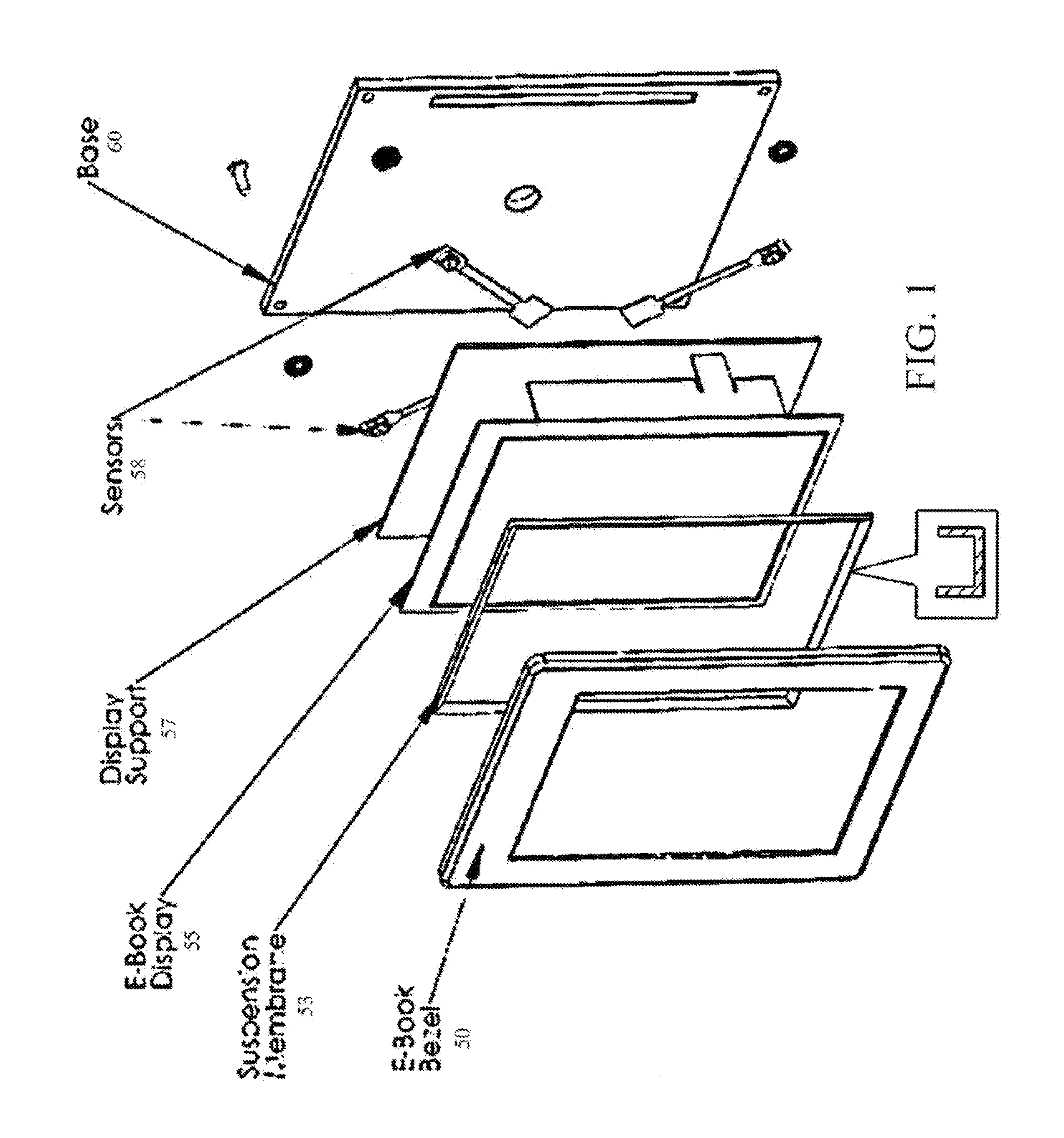
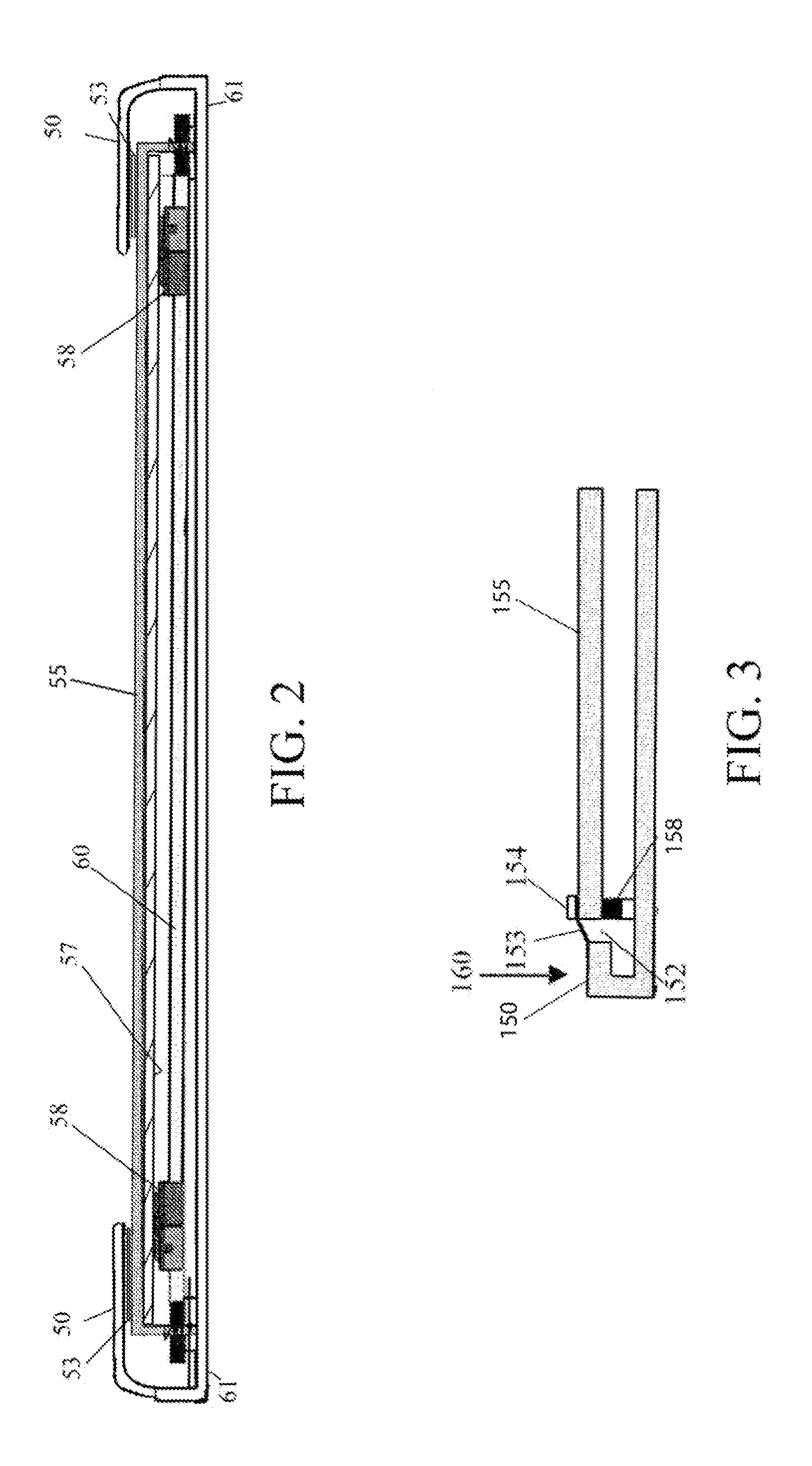
[0031]FIG. 1 is an exploded view of a suspension platform according to one embodiment of the present invention incorporated in a touch sensitive input display for an eBook reader, and FIG. 2 is a side view.

[0032]In an embodiment, an eBook reader comprises an ePaper display (EPD) that is a touch surface 55 defining an x-y plane having a normal z-axis. The reader housing incorporates a bezel 50 that defines a touch plane on the touch surface 55. The bezel 50 is held in place by connecting it to a back housing 61 (see FIG. 2) of the eReader housing. The bezel 50 is also connected to a thin suspension membrane 53. The bezel ...


PUM


Abstract

A suspension system for mounting a touch surface of a pressure sensitive touch display or panel. The suspension system comprises a frame and a flexible suspension membrane connected to the touch surface and the frame, the membrane allowing frictionless movement of the touch surface along the z-axis and resisting movement of the touch surface within the x-y plane. At least one force sensor is connected beneath the touch surface, whereby the touch surface is pre-loaded against the at least one force sensor.

Description

CROSS-REFERENCE TO RELATED APPLICATION(S)[0001]This application claims the benefit of U.S. Provisional Application No. 61 / 270,344, filed Jul. 7, 2009, which is a continuation-in-part of International Application No. PCT / US2008 / 003374, filed Mar. 14, 2008, both of which are incorporated by reference.BACKGROUND OF THE INVENTION[0002]1. Field of the Invention[0003]The present invention relates generally to input devices for electronics and, more particularly, to a suspension for a touch sensitive input panel's or display's touch surface especially suited for use in eBook readers, cellular phones and personal digital assistants (PDAs), PC Tablets, as well as laptops, PCs, office equipment, medical equipment, TVs Monitors, or any other device that uses touch sensitive displays or panels.[0004]2. Description of the Background[0005]Touch sensitive screens or touch surfaces can detect the application of fingers and other passive objects. Touch surfaces are gaining in popularity and have bee...

Claims


Application Information

Patent Timeline
Patent Type & Authority Applications(United States)
IPC IPC(8): H05K7/00
CPCG06F3/03547H01H2219/024H01H9/025G06F3/0414G06F3/04142
Inventor GRIFFITH, DAVIDSMITH, GARYLACKEY, MARKMOLNE, ANDERS
Owner APPLE INC
Learn More