
Handheld cleaning appliance

a cleaning appliance and hand-held technology, applied in the field of hand-held vacuum cleaners, can solve the problems of affecting the performance of the appliance, affecting the cleaning effect of the appliance, and inconvenient and messy portion replacement,

Inactive Publication Date: 2009-12-17
DYSON TECH LTD
View PDF4 Cites 112 Cited by
  • Summary
  • Abstract
  • Description
  • Claims
  • Application Information

AI Technical Summary

Benefits of technology

The invention is a handheld cleaning appliance with a separating apparatus for dirt and dust from air. The appliance has a cyclonic separator and a collector with a wall and base member. The base member is held in a closed position by a catch and is pivotably connected to the wall. The appliance also includes a main body with an actuator for operating the catch. The actuator has a slidably mounted rod which is movable between an inoperative position and an actuating position in which the rod contacts part of the catch so as to allow the collector to be opened for emptying purposes. This arrangement allows the catch to be released without the user actually touching the collector. It also provides a compact, reliable mechanism for remotely emptying the collector in a cost-efficient manner.

Problems solved by technology

A disadvantage of known handheld vacuum cleaners which utilise cyclonic separators is that emptying the appliance of dirt and dust collected therein can be awkward, inconvenient and messy.
Removal of a portion of the appliance inevitably carries with it a risk that the portion will not be replaced correctly and this can adversely affect the performance of the appliance.
In other arrangements, the opening of the compartment in which the dirt and dust is collected involves awkward manipulation of the appliance as a whole.
When the appliance has been designed for ease of handling during the cleaning operation, the emptying process can increase the risk of the appliance being inadvertently dropped and broken during emptying.

Method used


Image

  • Handheld cleaning appliance
  • Handheld cleaning appliance
  • Handheld cleaning appliance

Examples


Embodiment Construction

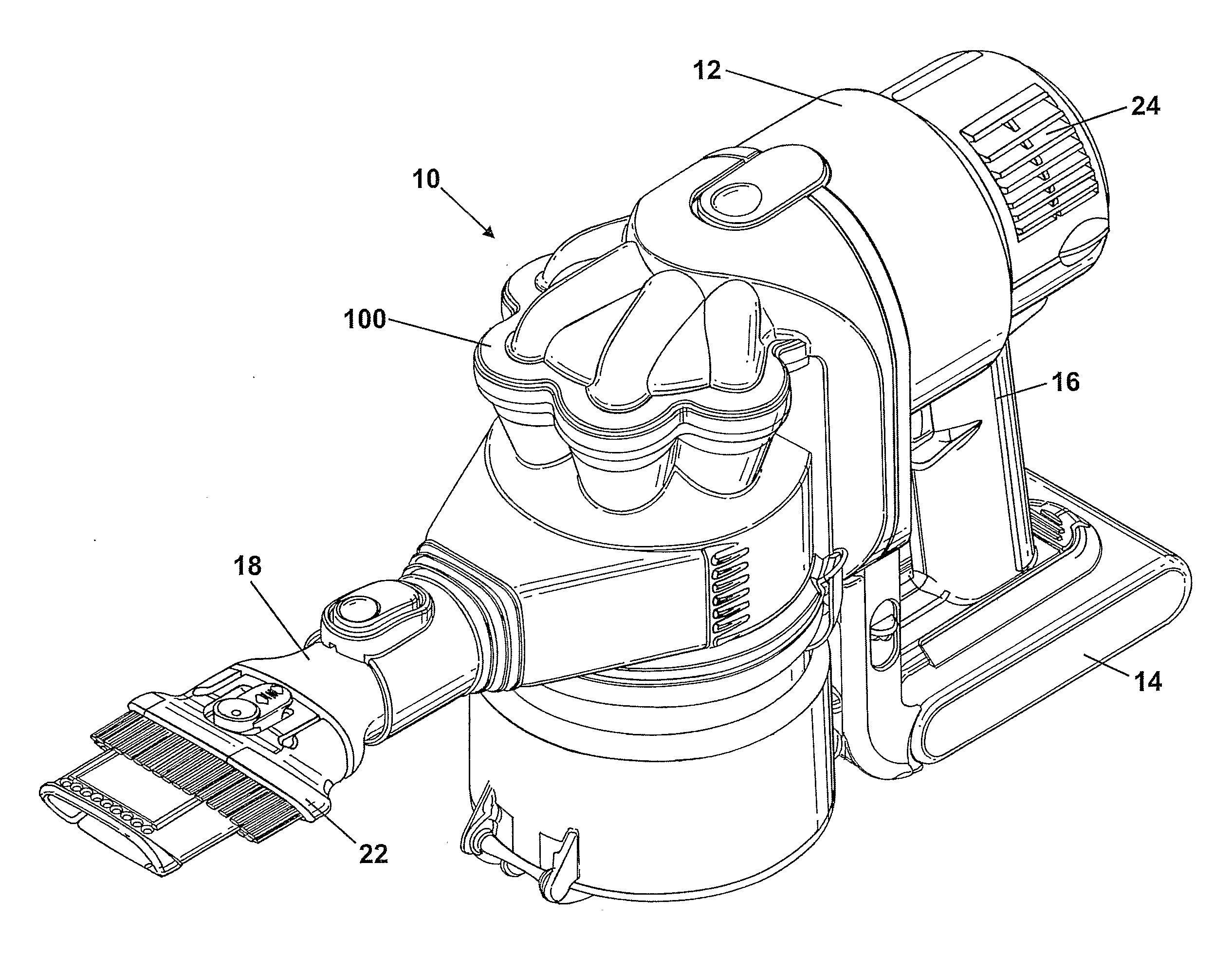
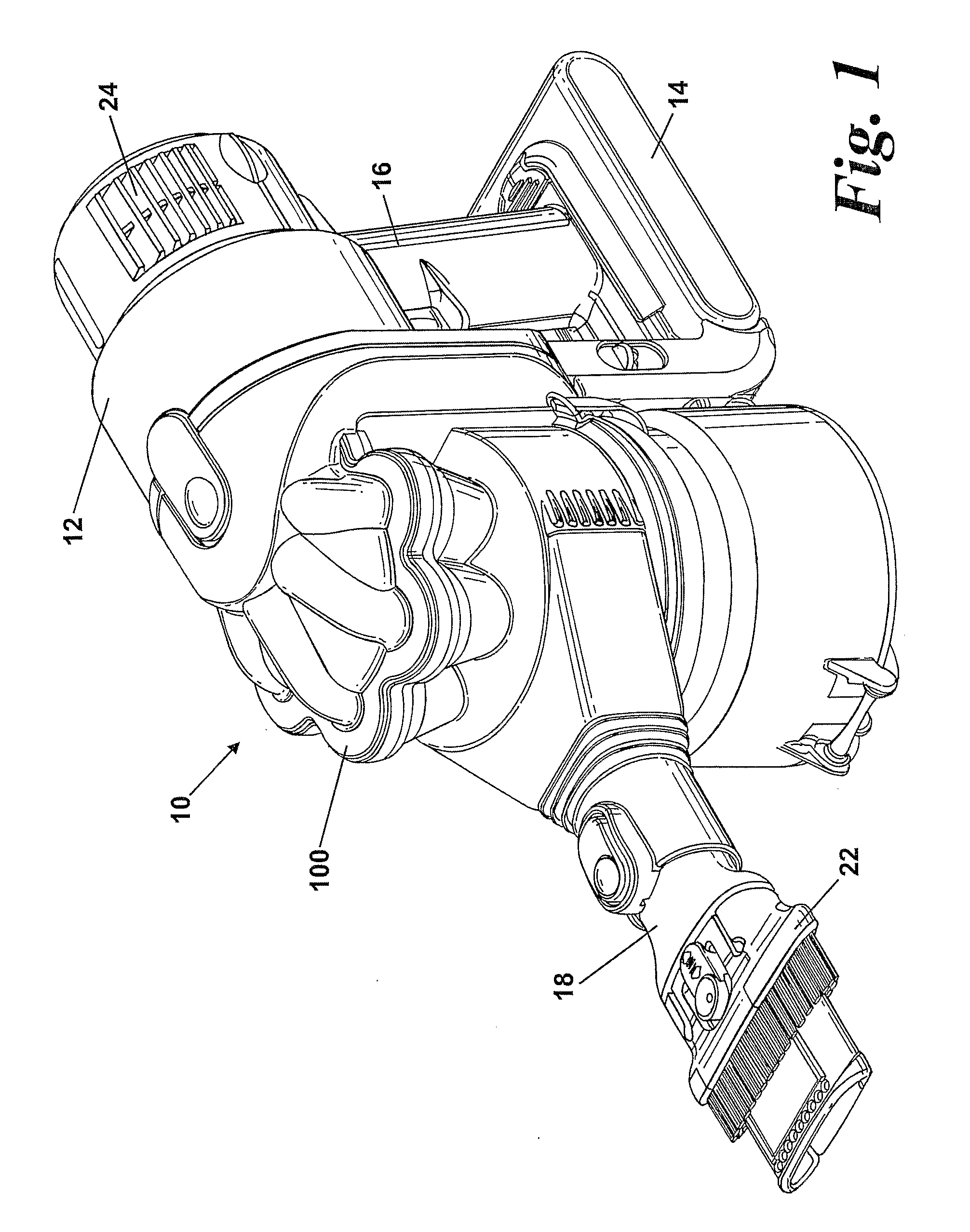
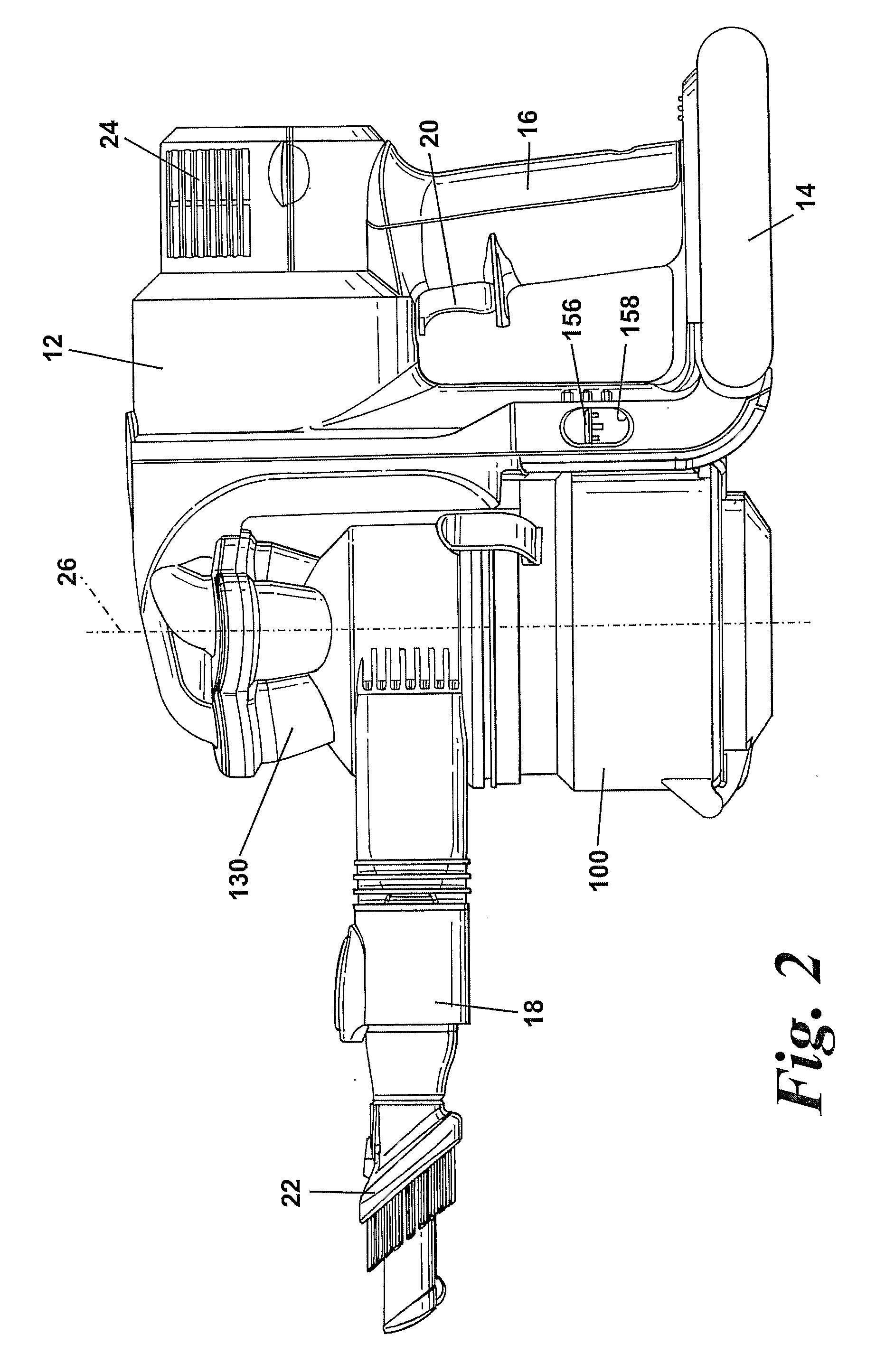
[0013]FIGS. 1 to 3 show a handheld vacuum cleaner 10. The handheld vacuum cleaner 10 has a main body 12 which houses a motor and fan unit (not shown). The main body 12 also includes a power source 14 such as a battery. A handle 16 is provided on the main body 12 for manipulating the handheld vacuum cleaner 10 in use. A cyclonic separator 100 is attached to the main body 12. A dirty air inlet 18 extends from a portion of the cyclonic separator 100 remote from the main body 12. A brush tool 22 is slidably mounted on the distal end of the dirty air inlet 18. A set of exhaust vents 24 are provided on the main body 12 for exhausting air from the handheld vacuum cleaner 10.

[0014]The cyclonic separator 100 is located between the main body 12 and the dirty air inlet 18. Consequently, the cyclonic separator 100 is located between the handle 16 and the dirty air inlet 18. The cyclonic separator 100 has a longitudinal axis 26 which extends in a generally upright direction so that the axis 26, ...


PUM


Abstract

A handheld cleaning appliance includes a dirty air inlet, a clean air outlet and separating apparatus for separating dirt and dust from an airflow in an airflow path leading from the air inlet to the air outlet. The separating apparatus includes a cyclonic separator having at least one cyclone and a collector having a wall and a base member, the base member being held in a closed position by a catch and being pivotably connected to the wall. The appliance further includes a main body which incorporates an actuator for operating the catch. The actuator has a slidably mounted rod which is movable between an inoperative position and an actuating position in which the rod contacts part of the catch so as to allow the collector to be opened for emptying purposes. This arrangement allows the catch to be released without the user actually touching the collector.

Description

REFERENCE TO RELATED APPLICATIONS[0001]This application is a national stage application under 35 USC 371 of International Application No. PCT / GB2007 / 002543, filed Jul. 6, 2007, which claims the priority of United Kingdom Application Nos. 0614237.6 and 0618494.9, filed Jul. 18, 2006, and Sep. 20, 2006, respectively, the contents of which prior applications are incorporated herein by reference.FIELD OF THE INVENTION[0002]The invention relates to a handheld cleaning appliance particularly, but not exclusively, to a handheld vacuum cleaner. More particularly, the invention relates to a handheld cleaning appliance having a cyclonic separator.BACKGROUND OF THE INVENTION[0003]Handheld vacuum cleaners are well known and have been manufactured and sold by various manufacturers for several years. Typically, a handheld vacuum cleaner comprises a casing which houses a motor and fan unit for drawing air into the cleaner via an inlet, and a separation device such as a filter or bag for separating...

Claims


Application Information

Patent Timeline
Patent Type & Authority Applications(United States)
IPC IPC(8): A47L5/24
CPCA47L5/24A47L9/1625A47L9/1641A47L9/1683B04C5/08Y10S55/03B04C5/103B04C5/13B04C5/185B04C5/26B04C2009/002B04C5/10A47L5/00A47L9/16A47L9/1608A47L9/1691A47L9/1616B04C5/081A47L5/26
Inventor MILNE, WILLIAM FRAMEWHITE, WILLIAM ROBERT JAMES
Owner DYSON TECH LTD
Learn More