Fluid pump/generator with integrated motor and related stator and rotor and method of pumping fluid

a technology of fluid pump and motor, which is applied in the direction of positive displacement liquid engine, electric generator control, piston pump, etc., can solve the problems of low reliability due to the interaction between motor and pump, high energy consumption due to the cooling of motor, and economic inefficiency, so as to improve the reliability of the device, reduce the number of parts, and increase the cost

Inactive Publication Date: 2006-04-04
ADVANCED ENERGY CONVERSION
View PDF17 Cites 117 Cited by
  • Summary
  • Abstract
  • Description
  • Claims
  • Application Information

AI Technical Summary

Benefits of technology

[0011]The present invention includes a fluid pump integrated with a motor, a fluid pump / generator device, a rotor for a fluid pump / generator device, a stator for a fluid pump / generator device and a method for pumping fluid. Specifically, a fluid pump includes a motor rotor having a plurality of magnetic vanes that electromagnetically interact with a plurality of magnetic poles of the motor stator such that the rotor functions simultaneously as the impeller for the pump and rotor for the motor, with fluid flowing through channels on the rotor. Pump and motor are tightly integrated into one single device so that the number of parts is reduced, total size is compressed, reliability of the device is improved, and cost efficiency is increased. The fluid flow is used to directly cool the pump / generator device, which reduces the size of the generator.

Problems solved by technology

The disadvantages of the conventional pump, inter alia, includes: economic inefficiency due to the use of both motor and pump and increased parts; higher energy consumption due to the cooling of motor; low reliability due to the interaction between motor and pump; and increased size.
However, removal of material from the rotor to form the recessions fundamentally limits efficiency because motor efficiency will tend to drop as additional material is removed from the rotor for the sake of improving pumping efficiency.

Method used


Image

  • Fluid pump/generator with integrated motor and related stator and rotor and method of pumping fluid
  • Fluid pump/generator with integrated motor and related stator and rotor and method of pumping fluid
  • Fluid pump/generator with integrated motor and related stator and rotor and method of pumping fluid

Examples


first embodiment

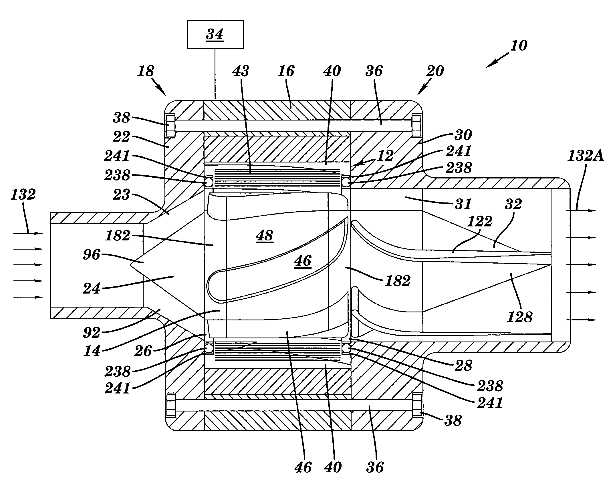
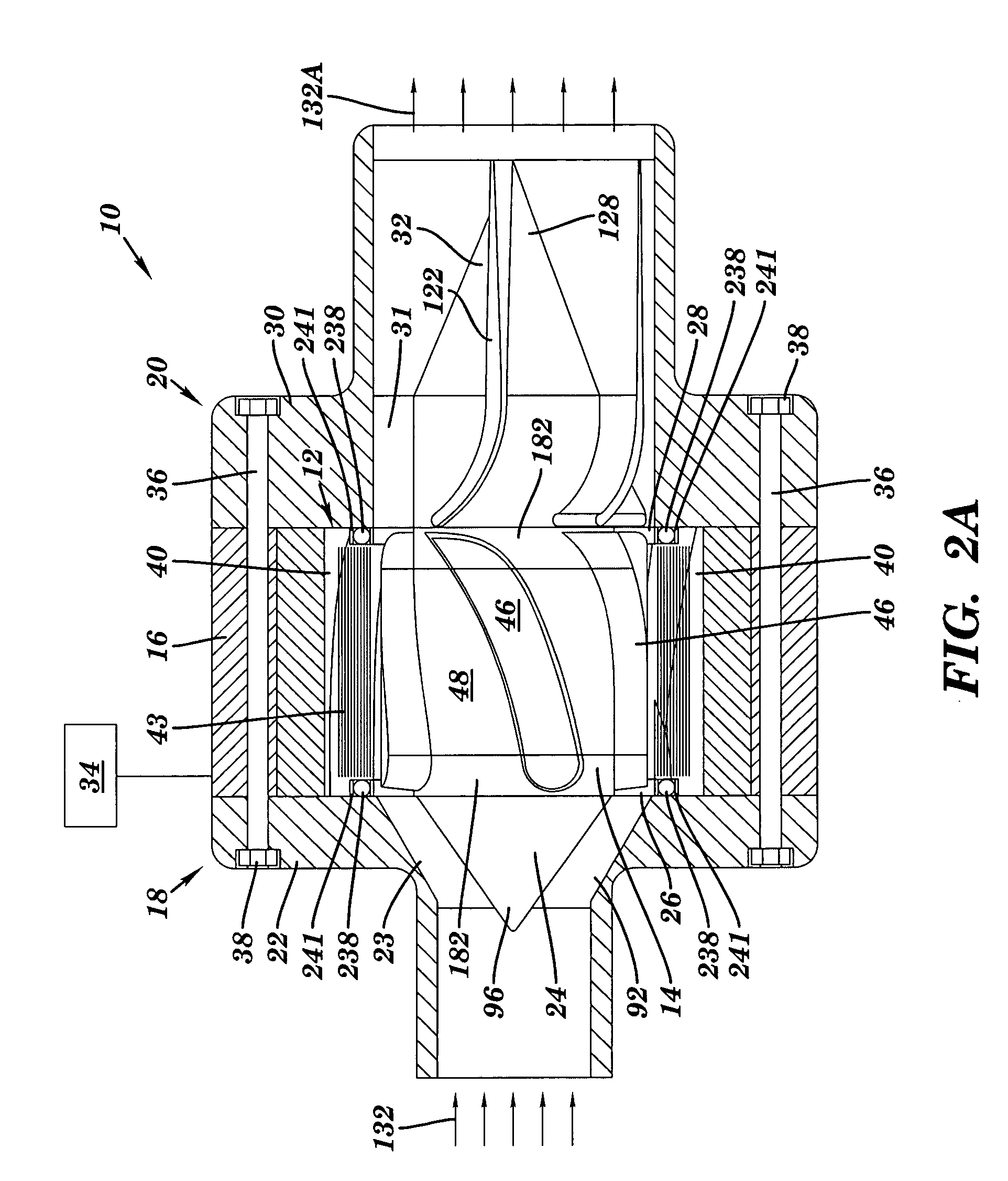
[0044]Fluid pump 10 can propel fluid in a number of ways. Turning to FIGS. 9 and 10 (also shown in FIGS. 2A–B), in a first embodiment, each magnetic pole 40 and / or magnetic vane 46 can include an angle relative to an axial direction of fluid pump 10 that is formed by circumferentially offsetting each (or a large number of) layer 50 of the respective member, i.e., stator or rotor, relative to an adjacent layer to form the angled shape in a process referred as “skewing.” That is, there is a circumferential rotation 82 of a layer 50A with respect to a layer 50B and a layer 50A. The angled shape of a vane 46 or pole 40 is partly determined by rotation 82 of one layer of magnetic material with respect to another and a thickness 84 of each layer. It is appreciated that the skewing need not be constrained to a fixed offset over the axial length of stator 12 and / or rotor 14. That is, vanes 46 and / or poles 40 may take a curved shape. By virtue of the salient magnetic sections, i.e., vanes an...

second embodiment

[0070]FIG. 20 and FIG. 21 show a fluid pump / generator device 310. In this embodiment, a fluid pump / generator 310 comprises at least two rotors 312A, 312B (or 312C and 312D in FIG. 21), with the magnetic vanes 346 of one rotor meshing with flow channels 348 of one another rotor. In the embodiments shown in FIGS. 20 and 21, a gear pump includes two rotors 312A, 312B (or 312C, 312D in FIG. 21), meshing with each other. The rotors 312A, 312B (or 312C, 312D in FIG. 21) being radially captured and enclosed by stators 314A, 314B (or 314C, 314D in FIG. 21), with the stators having a plurality of magnetic poles 340, and at least one phase windings 343. The stators are included in housing 316. The rotors include a plurality of magnetic vanes 346, and a plurality of channels 348, the plurality of magnetic vanes 346 each having an involute shape as described above (and shown in FIG. 8). The magnetic vanes 346 of one rotor meshing with flow channels 348 of the other rotor. FIG. 20 shows stators ...


PUM


Abstract

A fluid pump integrated with a motor, a fluid pump / generator device, a rotor for a fluid pump / generator device, a stator for a fluid pump / generator device and a method for pumping fluid are disclosed. Specifically, a fluid pump includes a motor rotor having a plurality of magnetic vanes that electromagnetically interact with a plurality of magnetic poles of the motor stator such that the rotor functions simultaneously as the impeller for the pump and rotor for the motor, with fluid flowing through channels on the rotor. Pump and motor are tightly integrated into one single device so that the number of parts is reduced, total size is compressed, reliability of the device is improved, and cost efficiency is increased. In addition, the use of magnetic vanes for propelling fluid improves motor efficiency. Further, the fluid flow is used to directly cool the pump / generator device, which reduces energy consumption.

Description

[0001]This application claims the benefit of U.S. Provisional Application No. 60 / 482,403, filed Jun. 25, 2003, under 35 U.S.C. 119(e).BACKGROUND OF THE INVENTION[0002]1. Technical Field[0003]The present invention relates to a fluid pump / generator. Specifically, a fluid pump / generator in which the rotor includes magnetic vanes that act as an impeller and interact with magnetic poles of the stator.[0004]2. Related Art[0005]In conventional electrically driven pumps, the pump and motor are connected through a shaft and the pump and the motor are each contained within their own housing. The disadvantages of the conventional pump, inter alia, includes: economic inefficiency due to the use of both motor and pump and increased parts; higher energy consumption due to the cooling of motor; low reliability due to the interaction between motor and pump; and increased size. Some previous attempts have been made to eliminate these disadvantages of a conventional pump.[0006]Allen et al. (U.S. Pat....

Claims


Application Information

Patent Timeline
Patent Type & Authority Patents(United States)
IPC IPC(8): F04B17/03F04C2/18F04C15/00F04D3/00F04D13/06
CPCF04C2/18F04D13/064F04D3/00F04C15/008
Inventor TORREY, DAVID A.KIRCHNER, EDWARD C.
Owner ADVANCED ENERGY CONVERSION
Why Eureka
Try Eureka