Fiber optic pressure sensor for catheter use

a fiber optic and pressure sensor technology, applied in optics, instruments, catheters, etc., can solve the problems of poor compatibility with actual catheter design, strong influence on the fidelity of pressure measurement, and limited use, and achieve low thermal shift, high fidelity measurement, and low cost

Active Publication Date: 2010-03-30
OPSENS
View PDF17 Cites 100 Cited by
  • Summary
  • Abstract
  • Description
  • Claims
  • Application Information

AI Technical Summary

Benefits of technology

[0018]The invention provides a miniature robust fiber optic pressure sensor that can be produced at a fairly low cost, delivering high fidelity measurements and low thermal shift, while not being prone to moisture drift. The miniature fiber optic sensor comprises a Fabry-Perot chip bonded to an optical fiber. The invention provides a new sensor design that reduces the amount of adhesive required to bond the optical fiber to the Fabry-Perot sensor such that the sensor is less sensitive to moisture. The invention also provides manufacturing methods of the sensor comprising a method based on etching and a method based on using an excimer laser. The invention also provides a chip design that renders the chip less sensitive to thermal changes. The invention also provides a chip design that provides a sensor diaphragm having a well-defined thickness. The invention also provides a chip design that protects the chip from etching.

Problems solved by technology

This method suffers however from its extreme sensitivity against tubing movement which strongly affect the fidelity of the pressure measurement.
In addition, for the tubing to properly transmit the dynamic of the pressure, it must be relatively large which provides poor compatibility with actual catheter design.
On the other hand, their use is limited to areas where no electromagnetic noise is present, such as in presence of MRI or electrosurgery.
Another drawback of those electrical sensors is their sensitivity to moisture drift that results from the change of the conductivity of the media surrounding the pressure chip.
Those sensors are well known to be prone to fluctuations due to all sort of environmental effects.
For instance, bonding the pressure chip using solder glass makes the process very expensive, raising the cost to a level not compatible with medical uses.
The pressure chip could be bonded on tip of the optical fiber using a polymer, but the cost would remain high because the tip of the fiber optic under this circumstance needs to be processed to receive the chip.
Notwithstanding the additional cost, the use of a polymer nearby the Fabry-Perot cavity makes this design prone to moisture induced drifting due to adhesive swelling.
On the other hand, this design can in no circumstance provide any stable pressure measurement.
Since the tip of the optical fiber constitutes the first mirror of the Fabry-Perot cavity, the pressure measurement becomes functions of any fiber optic unavoidable pistoning due to moisture, temperature and handling.
One important drawback of this method remains its sensitivity to moisture drift.
Upon swelling, the polymer that fills the silicon funnel for holding the optical fiber in place will induce a bending force to the pressure chip that brings the mirrors in closer proximity and thus, inducing drift.
Although the use of an optical lens 8 can be considered, this does not yet resolve the method for attaching the fiber 9 to the glass substrate so that no environmental parasitic effect will be detrimental to the pressure measurement.
Also, the insertion of the optical fiber 9 into the tube 13 contributes increasing the production cost.
Thus one drawback of current Fabry-Perot pressure sensors is their sensitivity to moisture.
Another drawback of Fabry-Perot pressure sensors is their sensitivity to temperature.
Another drawback of the actual sensors is the variation in their sensitivity when immersed into a water based solution, phenomenon usually erroneously associated to moisture drift.

Method used


Image

  • Fiber optic pressure sensor for catheter use
  • Fiber optic pressure sensor for catheter use
  • Fiber optic pressure sensor for catheter use

Examples


Embodiment Construction

[0037]In the following description of the embodiments, references to the accompanying drawings are by way of illustration of an example by which the invention may be practiced. It will be understood that other embodiments may be made without departing from the scope of the invention disclosed.

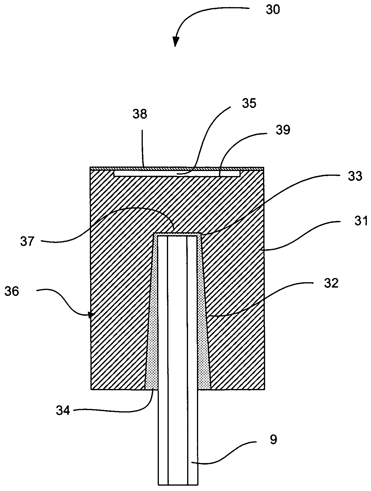
[0038]Referring now to FIG. 4, there is shown a fiber optic Fabry-Perot pressure sensor 30, in accordance with a first embodiment of the present invention that is less sensitive to moisture induced drift then prior designs. The sensor 30 comprises a pressure chip 36 that is coupled to an optical fiber 9. The pressure chip 36 comprises a recessed cavity 39 covered by a diaphragm 38 forming the Fabry-Perot cavity 35. By way of non limiting example, a glass substrate 31 500 microns in thickness is first drilled with tiny holes 33 accommodating the fiber optic 9 to a thickness of 300 microns. It is understood by those skilled in the art that other combination of glass substrate thickness and drilli...


PUM


Abstract

The invention provides a miniature robust fiber optic pressure sensor. The miniature fiber optic sensor comprises a Fabry-Perot chip bonded to an optical fiber. The invention provides a new sensor design that reduces the amount of adhesive required to bond the optical fiber to the Fabry-Perot sensor such that the sensor is less sensitive to moisture. The invention also provides manufacturing methods of the sensor comprising a method based on etching and a method based on using an excimer laser. The invention also provides a chip design that renders the chip less sensitive to thermal changes. The invention also provides a chip design in which a sensor diaphragm has a well-defined thickness. The invention also provides a chip design that protects the chip from etching.

Description

CROSS-REFERENCE TO RELATED APPLICATIONS[0001]This application claims priority under 35USC§119(e) of U.S. provisional patent application 60 / 637,755 filed Dec. 22, 2004, the specification of which is hereby incorporated by reference.FIELD OF INVENTION[0002]The invention relates to pressure sensor for in-vivo measurements and more specifically, to catheter tip fiber optic pressure sensor.BACKGROUND OF THE INVENTION[0003]The use of catheters is sharply increasing in a number of diagnostic and therapeutics procedures, leading to less invasive diagnostics and therapy. It is often required to perform pressure measurement of internal tissues or fluids. It is always of the utmost importance to have the capability of reducing the size of the catheter and thus, the pressure sensor must be as small as possible. Other important features for a pressure sensor are fidelity and stability.[0004]Among the first invasive pressure sensors used in combination with catheters were external and were connec...

Claims


Application Information

Patent Timeline
Patent Type & Authority Patents(United States)
IPC IPC(8): G02B6/00
CPCG01L9/0079A61B5/0215G01L19/04
Inventor BELLEVILLE, CLAUDEBUSSIERE, SYLVAINVAN NESTE, RICHARD
Owner OPSENS
Why Eureka
Try Eureka