

Light-emitting device, production method therefor, and display containing the same
a light-emitting device and production method technology, applied in the direction of solid-state devices, electric lighting sources, electric light sources, etc., can solve the problems of low light-extraction efficiency, inability to achieve satisfactory light-extraction efficiency, so as to improve light-extraction efficiency and front brightness
- Summary
- Abstract
- Description
- Claims
- Application Information
AI Technical Summary
Benefits of technology
Problems solved by technology
Method used
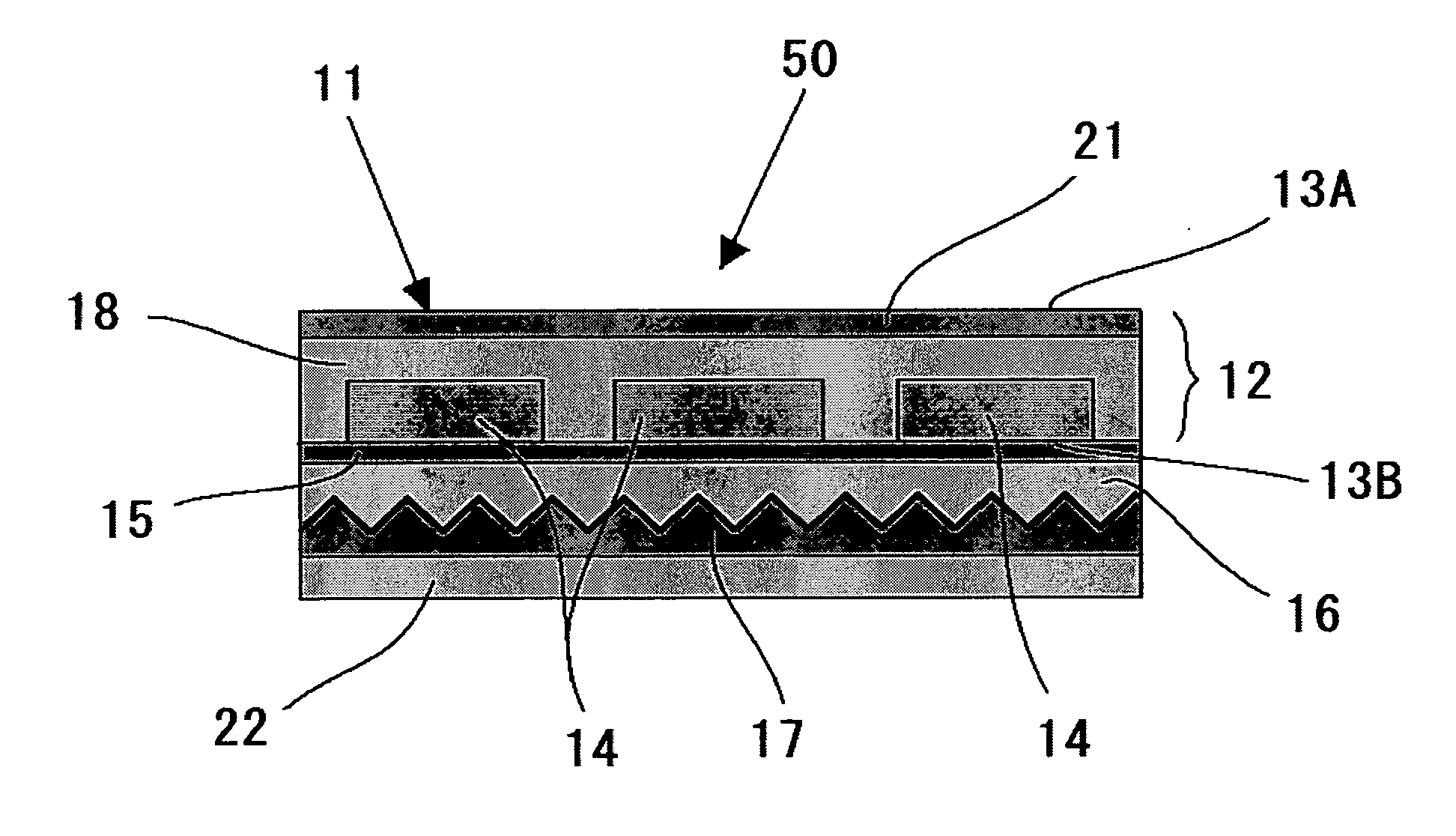
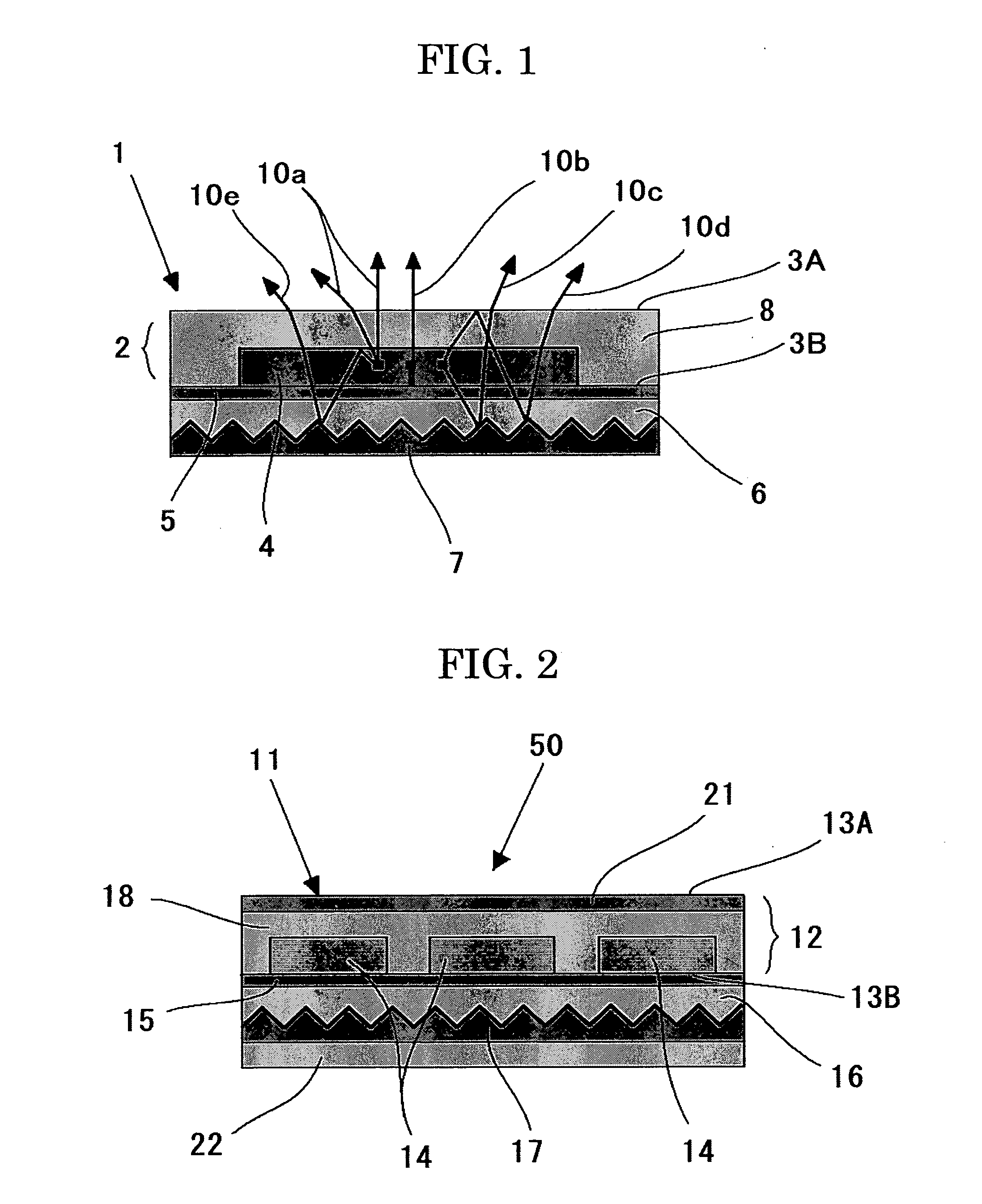
Image


Examples
example 1
[0244]A light-emitting device of Example 1 was fabricated as follows.
[0245]Through the below procedure, a fine concavo-convex pattern was formed and then provided with a reflective layer over one surface thereof.
>
[0246]A thin film was formed on a glass substrate using compound A given below; i.e., an ionically-bonded compound of the upper and lower compounds (compound A has a high refractive index: n5=1.73 with respect to light having a wavelength of 550 nm (main light-emitting wavelength)).
[0247]A material made of compound A (35 mg) was dissolved in tetrafluoropropanol (1 mL). The resultant solution was dropped on the glass substrate which was being rotated at 300 rpm. Then, the rotation speed was increased to 1,000 rpm, whereby a 200 nm-thick thin film was formed.
[0248]The thin film was treated using a fine processing device (NEO1000, product of Pulstec Industrial Co., Ltd.) to form a fine concavo-convex pattern having a pitch interval of 0.6λ.
[0249]>
[0250]Through DC sputtering, a...
example 2
[0263]The procedure of Example 1 was repeated, except that three interference layers were formed, to thereby fabricate a light-emitting device of Example 2.
example 3
[0264]The procedure of Example 1 was repeated, except that five interference layers were formed, to thereby fabricate a light-emitting device of Example 3.
PUM
 Abstract
Description
Claims
Application Information