Gas internal combustion type nailing machine

a nailing machine and internal combustion technology, applied in the direction of nailing tools, manufacturing tools, stapling tools, etc., can solve the problems of inability to provide a proper air-fuel ratio, mixed fuel cannot be combusted, and can only be combusted incompletely, so as to secure the durability and safety of the nailing machine

Inactive Publication Date: 2010-05-06
MAX CO LTD
View PDF11 Cites 34 Cited by
  • Summary
  • Abstract
  • Description
  • Claims
  • Application Information

AI Technical Summary

Benefits of technology

[0008]One or more embodiments of the invention provide a gas internal combustion type nailing machine that carries out special measures such as a cutoff of a fuel supply, a disabling of an operation of a spark plug, and a reduction of a supercharge pressure through expansion of a volume of an inside of a combustion chamber, when the supercharge pressure exceeds a set pressure value, so as to prevent or restrict a generation of an excessive combustion energy which exceeds a set output energy, thereby being able to secure a durability and a safety of the nailing machine.

Problems solved by technology

When, as the safety device, there is provided the control valve which is structured such that, when the supercharge pressure exceeds the set pressure value, it can cut off the supply of the fuel by the fuel supply device, even if the compressed air is supplied on in a state where the supercharge pressure exceeds the set pressure value, the supply of the fuel is cut off completely by the control valve, with the result that the mixed fuel within the combustion chamber is diluted to thereby be unable to provide a proper air-fuel ratio, whereby the mixed fuel cannot be combusted or can be combusted only incompletely.

Method used


Image

  • Gas internal combustion type nailing machine
  • Gas internal combustion type nailing machine
  • Gas internal combustion type nailing machine

Examples


first exemplary embodiment

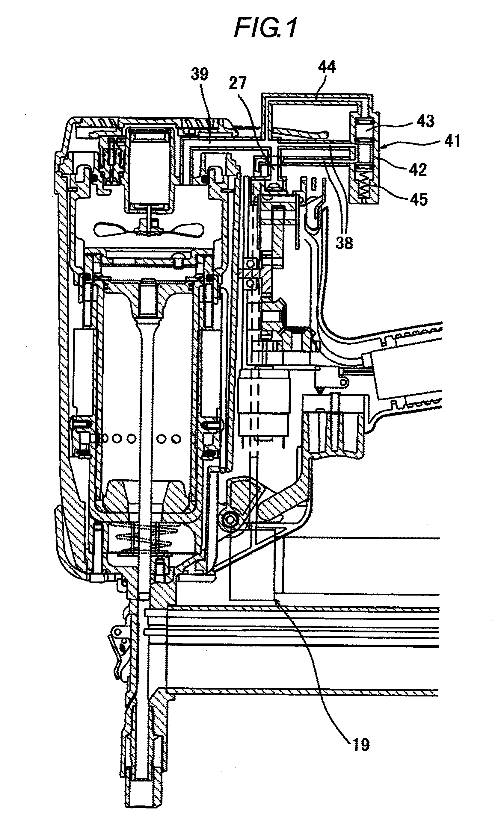
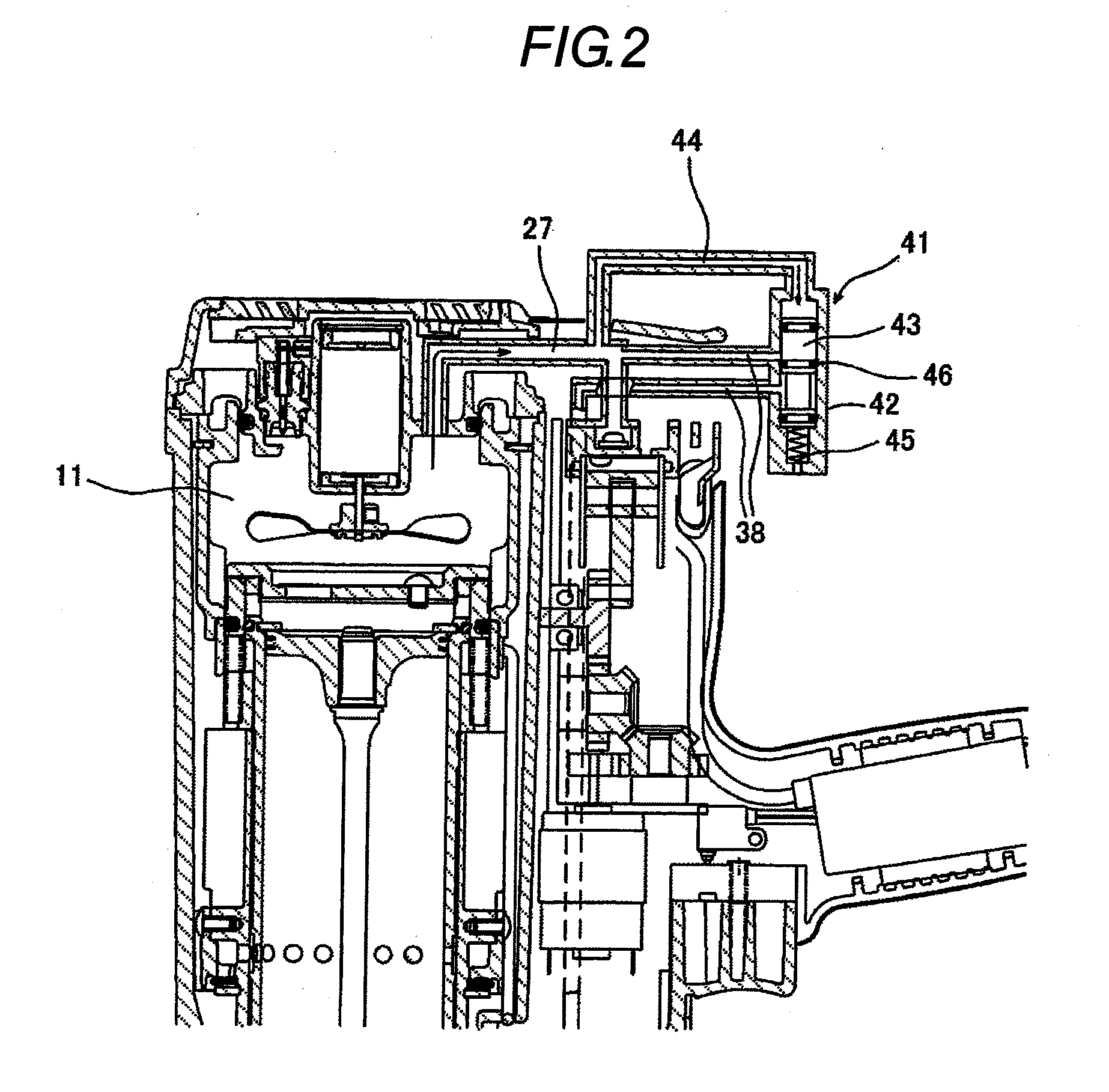
[0054]According to a first exemplary embodiment of the invention, the gas internal combustion nailing machine includes a device (a safety device) which, when the supercharge pressure generated by compressed air to be supplied into the combustion chamber 11 for supercharging exceeds a set pressure value, can cut off the supply of the fuel to be supplied by the fuel supply device.

[0055]That is, as shown in FIG. 1, in the intermediate portion of a fuel supply pipe 38 for supplying a fuel gas from a fuel supply device 19, there is provided a control valve 41 serving as the safety device. Within the valve cylinder 42 of the control valve 41, there is arranged a valve body 43 slidably and the upper end of the valve cylinder 42 is connected to a pressure take-out pipe 44 which diverges from a compressed air supply pipe 27. Also, downwardly of the valve cylinder 42, there is disposed a push-up spring 45 which is used to energize the valve body 43 upwardly. Further, the fuel supply pipe 38 o...

second exemplary embodiment

[0059]Next, description will be given below of a second exemplary embodiment according to the invention with reference to FIG. 3. According to the second exemplary embodiment, the nailing machine includes a device (a safety device) which, when the supercharge pressure generated by compressed air to be supplied into the combustion chamber 11 for supercharging exceeds a set pressure value, can release the supercharge pressure from within the combustion chamber 11 into the striking cylinder 5.

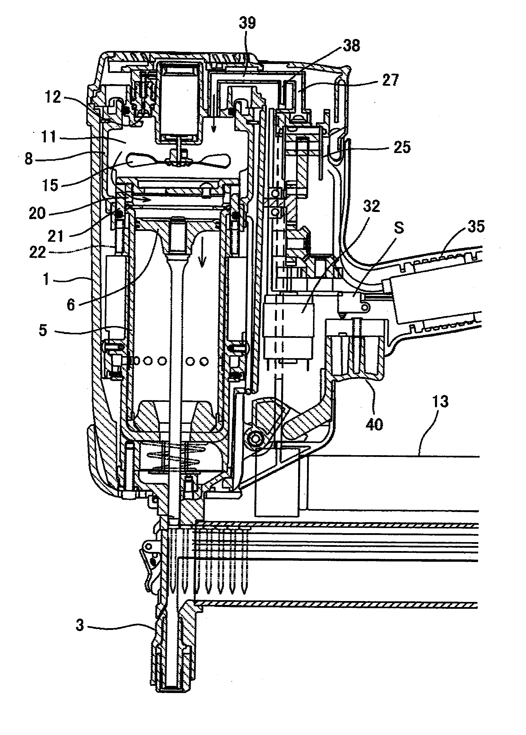
[0060]As described above, the gas fuel is supplied from the fuel supply device 19 (see FIG. 1) according to the supply amount of the compressed air to be supplied from a compressor 25, thereby being able to secure a proper air-fuel ratio. And, the compressed air supply pipe 27 and fuel supply pipe 38 are connected to each other directly; and, the fuel injected joins the compressed air and is then supplied from the compressed fuel supply pipe 39 into the combustion chamber 11.

[0061]Here, in the abo...

third exemplary embodiment

[0064]Next, description will be given below of a nailing machine according to a third exemplary embodiment of the invention with reference to FIG. 5.

[0065]According to a third exemplary embodiment of the invention, the nailing machine includes a device (a safety device) which controls the electric circuit of a control substrate 35 of an ignition control unit according to a detect signal from a pressure sensor 47 for detecting such pressure within the combustion chamber 11 as exceeding the above-mentioned set pressure value to thereby prevent a switch S, which is used to carry out the above-mentioned ignition, from being turned ON.

[0066]As shown in FIG. 5, on the side wall of the combustion chamber 11, there is mounted the pressure sensor 47; and, when the supercharge pressure within the combustion chamber 11 exceeds the set pressure value, the pressure sensor 47 detects this pressure state and emits a detect signal therefrom. And, the safety device is programmed such that, when the ...


PUM


Abstract

The present gas internal combustion type nailing machine is provided with: a striking cylinder for slidably accommodating a striking piston therein; a combustion chamber formed in an upper side and capable of being opened and closed; a compressor for supercharging compressed air into the combustion chamber; a fuel supply device for supplying a fuel gas into the combustion chamber; and a safety device for preventing the nailing machine from being driven for ignition when the supercharge pressure of the compressed air exceeds a set pressure value.

Description

TECHNICAL FIELD[0001]The present invention relates to a gas internal combustion type nailing machine. Specifically, the invention relates to a gas internal combustion type nailing machine which takes measures to cope with an unexpected increase in supercharge pressure.BACKGROUND ART[0002]A gas internal combustion type nailing machine is conventionally known (for example, see the patent reference 1) and, in this type of nailing machine, there is also known a nailing machine which aims at increasing the output energy thereof by supercharging compressed air into a combustion chamber.[0003]In these well-known gas internal combustion type nailing machines, there are taken measures to maintain a proper air-fuel ratio in order to secure a good combustion state and, for this purpose, there is provided means for adjusting a fuel injection amount based on an air supply amount into the combustion chamber.[0004]For example, a certain known gas internal combustion type nailing machine of a super...

Claims


Application Information

Patent Timeline
Patent Type & Authority Applications(United States)
IPC IPC(8): B25C1/08
CPCB25C1/008B25C1/08B25C1/18F02B39/16F02B63/02
Inventor TANAKA, HIROSHI
Owner MAX CO LTD
Why Eureka
Try Eureka