Water decomposition device and method of manufacturing the same

a technology of water decomposition device and manufacturing method, which is applied in the direction of electrolysis components, transportation and packaging, lighting and heating apparatus, etc., can solve the problems of easy stains after use, large temperature difference between the inside and the outside of the headlamp, and relatively short lifespan of the hydrophilic coating layer, etc., to achieve the effect of ensuring both transparency and durability

Active Publication Date: 2020-02-27
HYUNDAI MOTOR CO LTD +2
View PDF0 Cites 0 Cited by
  • Summary
  • Abstract
  • Description
  • Claims
  • Application Information

AI Technical Summary

Benefits of technology

[0009]Various aspects of the present invention are directed to providing a water decomposition device which may secure both transparency and durability even when an opaque material is used therefor.

Problems solved by technology

However, while the vehicle is operating, a great temperature difference occurs between the inside and the outside of the headlamp.
However, the hydrophilic coating layer has a relatively short lifespan, stains easily after use, and incurs relatively high costs.
However, in a high-humidity environment, such a moisture absorbent cannot be reused, and may deteriorate the light distribution capability of the headlamp due to the low transparency of the porous material.
However, when a heat-exchanging system or an air-conditioning system is used alone, it does not exhibit a sufficient effect compared to the amount of energy and costs that are required for the system.
Moreover, when the two systems are used together, the structure may become complicated.
In the case of a water decomposition technology using a hydrogen separator, there is a problem with bonding because it utilizes a polymer separator.
Thus, it is difficult to apply catalytic materials other than a precious metal such as platinum (Pt), iridium (Ir) or the like.
Furthermore, it is difficult to secure transparency of the structure thereof, and durability is also poor.

Method used


Image

  • Water decomposition device and method of manufacturing the same
  • Water decomposition device and method of manufacturing the same
  • Water decomposition device and method of manufacturing the same

Examples


example 1

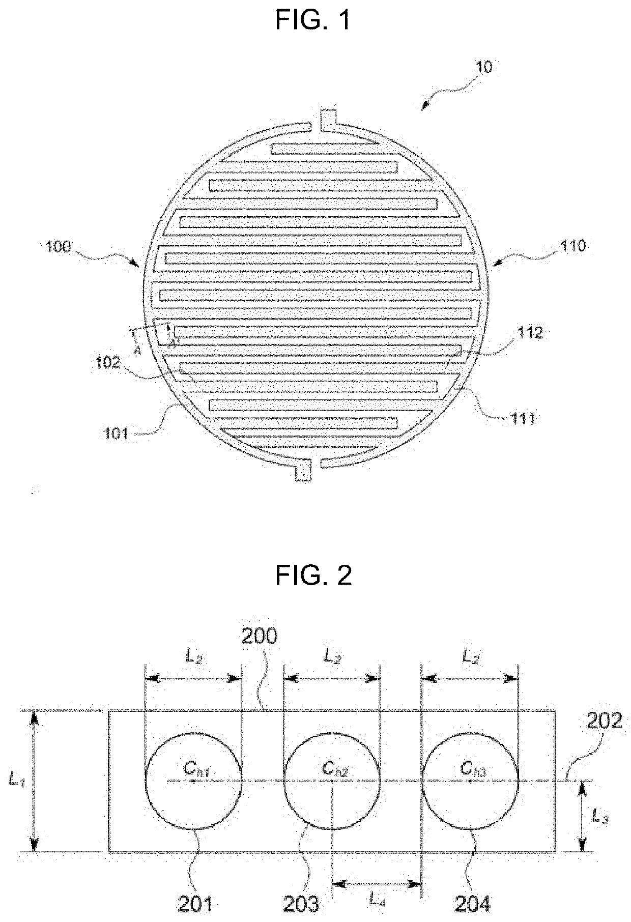
[0084]Polyethylene naphthalate was used to form a substrate. A first substrate was formed to have a ‘U’-shaped first external line and a first internal line, and a second substrate was formed to have a ‘U’-shaped second external line and a second internal line. Each of the first external line, the first internal line, the second external line and the second internal line was formed to have a width of 100 μm, and the interval between the first internal line and the second internal line was set to 100 μm. A plurality of circular holes, each having a diameter of 80 μm, was formed in each of the first external line, the second external line, the first internal line and the second internal line. The circular holes were formed such that the centers thereof were aligned with the center of the width of each of the lines, i.e., a point spaced from one side of each of the lines in the width direction thereof by 50 μm. The shortest distance from the center of one hole to another hole was set t...


PUM

PropertyMeasurementUnit
widthaaaaaaaaaa
diameteraaaaaaaaaa
distanceaaaaaaaaaa

Abstract

A water decomposition device may include a hydrogen-generating electrode including a first external electrode and at least one first internal electrode formed integrally with the first external electrode, and an oxygen-generating electrode including a second external electrode and at least one second internal electrode formed integrally with the second external electrode. The first external electrode and the second external electrode are disposed to face each other, and the first internal electrode and the second internal electrode are disposed alternately in a direction perpendicular to the longitudinal direction thereof. Therefore, the water decomposition device may secure both transparency and durability even when an opaque material is used therefor.

Description

CROSS-REFERENCE TO RELATED APPLICATION[0001]The present application claims priority to Korean Patent Application No. 10-2018-0097437, filed on Aug. 21, 2018 with the Korean Intellectual Property Office, the entire contents of which is incorporated herein for all purposes by this reference.BACKGROUND OF THE INVENTIONField of the Invention[0002]The present invention relates to a water decomposition device and a method of manufacturing the same, and more particularly to a water decomposition device including a hydrogen-generating electrode and an oxygen-generating electrode and to a method of manufacturing the same.Description of Related Art[0003]A vehicle headlamp is designed to illuminate an area in front of the vehicle. Such a headlamp must have sufficient light distribution capability for safe driving. However, while the vehicle is operating, a great temperature difference occurs between the inside and the outside of the headlamp. Particularly, in a high-humidity environment, for e...

Claims


Application Information

Patent Timeline
Patent Type & Authority Applications(United States)
IPC IPC(8): C25B1/04C25B11/02C01B3/06C25B9/06F21S45/33C25B9/17
CPCC01B3/068F21S45/33C25B11/02C25B9/06C25B1/04C25B9/00C25B11/03C25B11/051C25B11/069C25B11/091F21S45/30Y02E60/36C25B9/17C25D5/02
Inventor PARK, JANG SUKIM, HEE JUNLEE, TAEWONBAIK, JEONG MIN
Owner HYUNDAI MOTOR CO LTD
Why Eureka
Try Eureka