Tubular vibration-damping mount

US20120091643A1Active Publication Date: 2012-04-19PROSPIRA CORP

Image

  • Tubular vibration-damping mount
  • Tubular vibration-damping mount
  • Tubular vibration-damping mount

Examples


first embodiment

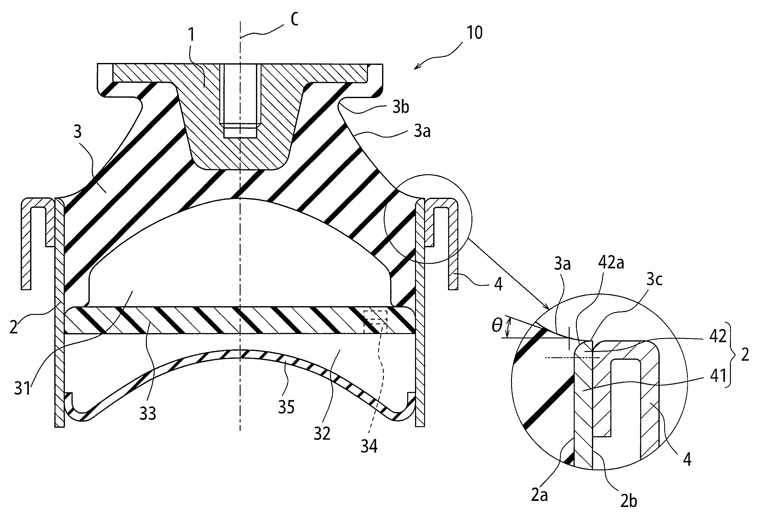
[0031]Embodiments of the present invention will be explained with reference to drawings. FIG. 4 is a sectional view showing a tubular vibration-damping mount of the A tubular vibration-damping mount 10 comprises a core member 1, a tubular member 2 located below the core member 1 and having an inside diameter larger than an outside diameter of the core member 1, a rubber member 3 located between these members 1 and 2 to couple these members 1 and 2 by vulcanization adhesion, and a bracket 4 supporting an outer periphery of the tubular member 2 with the tubular member 2 being inserted. An upper surface 3a of this rubber member 3 has a recessed portion 3b in a radially inner direction of the rubber member 3.

[0032]In this tubular vibration-damping mount 10, the tubular member 2 has, in an area higher than a lower end of an adhesion surface between the tubular member 2 and the rubber member 3, a straight cylindrical portion 41 which has an inner periphery 2a and an outer periphery 2b, b...

second embodiment

[0036]FIG. 5 is a sectional view showing a tubular vibration-damping mount of the Similar to the tubular vibration-damping mount 10, a tubular vibration-damping mount 20 also comprises a core member 11, a tubular member 12 located below the core member 11 and having an inside diameter larger than an outside diameter of the core member 11, a rubber member 13 located between these members 11 and 12 to couple these members 11 and 12 by vulcanization adhesion, and a bracket 14 supporting an outer periphery of the tubular member 12 with the tubular member 12 being inserted. An upper surface 13a of this rubber member 13 has a recessed portion 13b in a radially inner direction of the rubber member 13.

[0037]Also in this tubular vibration-damping mount 20, the tubular member 12 has, in an area higher than a lower end of an adhesion surface between the tubular member 12 and the rubber member 13, a straight cylindrical portion 21 which has an inner periphery 12a and an outer periphery 12b, bo...


PUM


Abstract

The present invention provides a tubular vibration-damping mount capable of securing durability against an input in a direction perpendicular to an axis. A tubular vibration-damping mount comprises a core member, a tubular member, a rubber member, an upper surface of which has, as viewed in a cross section including an axis of the core member, a recessed portion in a radially inner direction of the rubber member and an inclined portion whose inclination angle is smoothly and upwardly increased in the radially inner direction from a point on the tubular member as a starting point, and a bracket, wherein the tubular member has, in an area higher than a lower end of an adhesion surface between the tubular member and the rubber member and the upper surface of the rubber member starts from a point on the inner periphery of the diameter-enlarged portion of the tubular member, which the point agrees with the starting point.

Description

TECHNICAL FIELD[0001]The present invention relates to a tubular vibration-damping mount comprising: a core member; a tubular member located below the core member and having an inside diameter larger than an outside diameter of the core member; a rubber member located between the core member and the tubular member to couple the core member and the tubular member by vulcanization adhesion, an upper surface of the rubber member having, as viewed in a cross section including an axis of the core member, a recessed portion in a radially inner direction of the rubber member and an inclined portion whose inclination angle is smoothly and upwardly increased in the radially inner direction from a point on the tubular member as a starting point; and a bracket supporting an outer periphery of the tubular member with the tubular member being inserted. In particular, the present invention relates to a tubular vibration-damping mount capable of securing durability against an input in a direction p...

Claims


Application Information

Patent Timeline
19 Apr 2012
Publication
US20120091643A1
IPC
F16F7/00; F16F13/08
CPC
F16F13/103; F16F1/373
Inventors
MATSUDA, NAOHISA