Toroidal-type continuously variable transmission

a transmission device and continuously variable technology, applied in the direction of friction gearings, gearing elements, friction gearings, etc., can solve the problems of undesirable excessive large pressing force, excessive force generated by the loading cam type, and high production cost, so as to secure the transmission efficiency and durability of the toroidal-type continuously variable transmission. , the effect of reducing the transmission efficiency and durability of the toroidal-type continuously variable transmission

Inactive Publication Date: 2007-12-04
NSK LTD
View PDF13 Cites 2 Cited by
  • Summary
  • Abstract
  • Description
  • Claims
  • Application Information

AI Technical Summary

Benefits of technology

[0035]In view of the above-mentioned conventional structures, it is an object of the present invention to provide a structure which can be constructed in a simple manner, can provide proper surface pressures in the traction portions to thereby be able to secure the transmission efficiency and durability of a toroidal-type continuously variable transmission, and, even when disabled, can secure the minimum function.
[0039]In the case of the above-structured toroidal-type continuously variable transmission according to the invention, the pressing force to be generated by the pressing device is adjusted by the force (power) passing through the toroidal-type continuously variable transmission and the transmission ratio thereof; and, therefore, regardless of the operating states of the toroidal-type continuously variable transmission, the pressing force can be controlled to the optimum value. That is, the oil pressure to be introduced into the pressing device by the oil pressure correct device is set at a value obtained by subtracting a correction value from a target value set by a main oil pressure control unit, that is, a necessary value which varies according to a transmission ratio between the first and second disks and corresponds to the optimum value of the pressing force to be generated by the pressing device of the necessary value, the correction value can be obtained electrically and, therefore, the oil pressure to be introduced into the pressing device can be fine adjusted according to the operating states of the toroidal-type continuously variable transmission. As a result of this, the surface pressure of the traction portions can be set at a proper value, which makes it possible to secure the transmission efficiency and durability of the toroidal-type continuously variable transmission.
[0040]Also, in case where an electric circuit for obtaining the necessary value is out of order, the oil pressure correct device is unable to calculate the correction value, while the oil pressure of a target value set by the main oil pressure control unit is introduced into the pressing device. The target value exceeds the necessary value when the transmission ratio between the first and second disks is a speed reducing side or a speed increasing side. In other words, when the transmission ratio is the speed reducing side or the speed increasing side, the pressing force to be generated by the pressing device is excessively large. However, the pressing force to be generated in this case, in the first example of the conventional structures shown in the previously described FIGS. 4 to 6, corresponds to the pressing force that is generated by the pressing device 23 of a loading cam type. Therefore, the transmission efficiency and durability of the toroidal-type continuously variable transmission are lowered slightly, while the necessary minimum function can be secured. Thanks to this, not only a vehicle carrying the above-mentioned toroidal-type continuously variable transmission can be made to run by itself to a repair shop but also the inner surfaces of the first and second disks and the peripheral surfaces of the power rollers can be prevented against heavy damage.
[0041]Also, in case where the power to be transmitted between the first and second disks is detected in accordance with a difference between the values of oil pressures in a pair of oil pressure chambers formed in a cylinder portion constituting an actuator of an oil pressure type for shifting support members supporting the power rollers in the axial direction of their associated pivot shafts, the present power can be detected highly efficiently with a simple structure.
[0042]Further, in case where a correction signal is obtained while not only the transmission ratio but also the temperature of lubricating oil existing in the interior of the toroidal-type continuously variable transmission and the rotation speed of the drive source are taken into consideration, and the correction value of the oil pressure is obtained by opening and closing an electromagnetic valve in accordance with the thus-obtained correction signal, the surface pressures of the traction portions in the normal time (in the trouble-free time) can be set at more proper values and thus the transmission efficiency and durability of the toroidal-type continuously variable transmission can be secured more effectively.

Problems solved by technology

Of the above-mentioned conventional structures, in the case of the structure shown in FIGS. 4 and 5, the pressing force to be generated by the pressing device 23 of a loading cam type is often excessively large, which provides a disadvantage from the viewpoint of securing the durability of the composing parts of the toroidal-type continuously variable transmission 24.
The excessive large pressing force is undesirable not only from the viewpoint of reduction in the size of the toroidal-type continuously variable transmission, for securement of transmission efficiency but also from the viewpoint of securing the durability of the composing parts of the toroidal-type continuously variable transmission.
Therefore, the present structure cannot always provide a sufficient effect from the viewpoint of securement of transmission efficiency and from the viewpoint of securement of durability.
However, it is difficult to make such a fine adjustment as to reduce sufficiently a difference between a pressing force required and a pressing force occurring actually.
However, the present structure is not able to make a more detailed adjustment.
Also, not only it is difficult to measure the kinematic viscosity of the traction portion but also, even in case where such measurement is possible, it is unavoidable that the structure is complicated.
However, in case where the oil pressure to be introduced into the pressing device of an oil pressure type is controlled purely electrically, when a computer for control is out of order or when a control circuit is out of order due to breaking of a wire, the oil pressure disappears or lowers extremely.
As a result of this, the inner surfaces of the input side and output side disks and the peripheral surfaces of the power rollers, which are the composing parts of the toroidal-type continuously variable transmission, slip with respect to each other in their mutual rolling contact portions (that is, the above-mentioned traction portions), thereby causing so called gross slippage which makes it impossible to transmit the power between them.
In case where such gross slippage occurs, not only a vehicle carrying the toroidal-type continuously variable transmission becomes unable to run but also the respective surfaces wear excessively, thereby raising a possibility that the toroidal-type continuously variable transmission can be damaged to such a degree that the transmission cannot be repaired.
Therefore, in case where the oil pressure to be introduced into the pressing device of the above-mentioned oil pressure type is controlled only by the control circuit of a purely electrical type, there arises a problem from the viewpoint of securement of reliability.

Method used


Image

  • Toroidal-type continuously variable transmission
  • Toroidal-type continuously variable transmission
  • Toroidal-type continuously variable transmission

Examples


Embodiment Construction

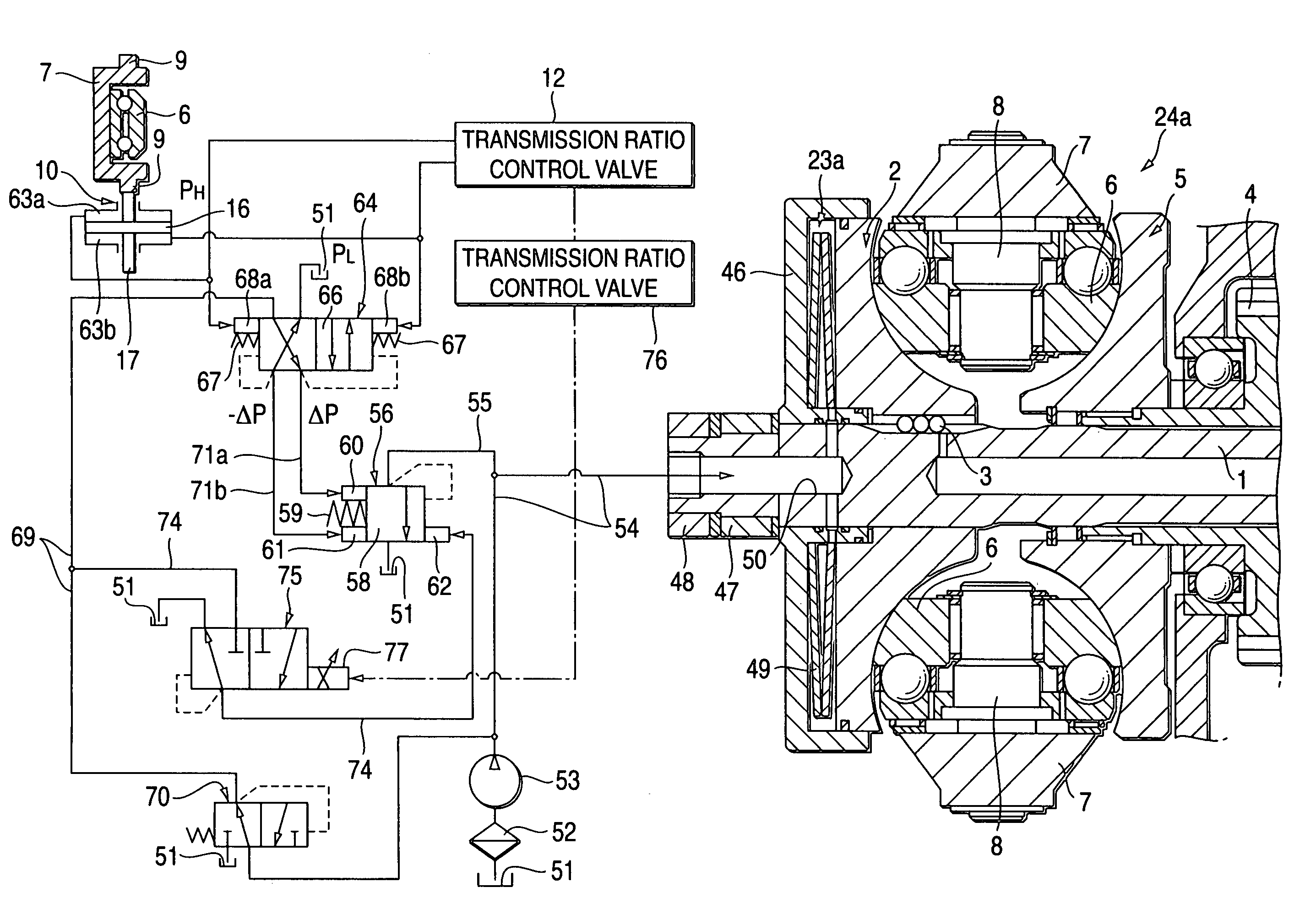
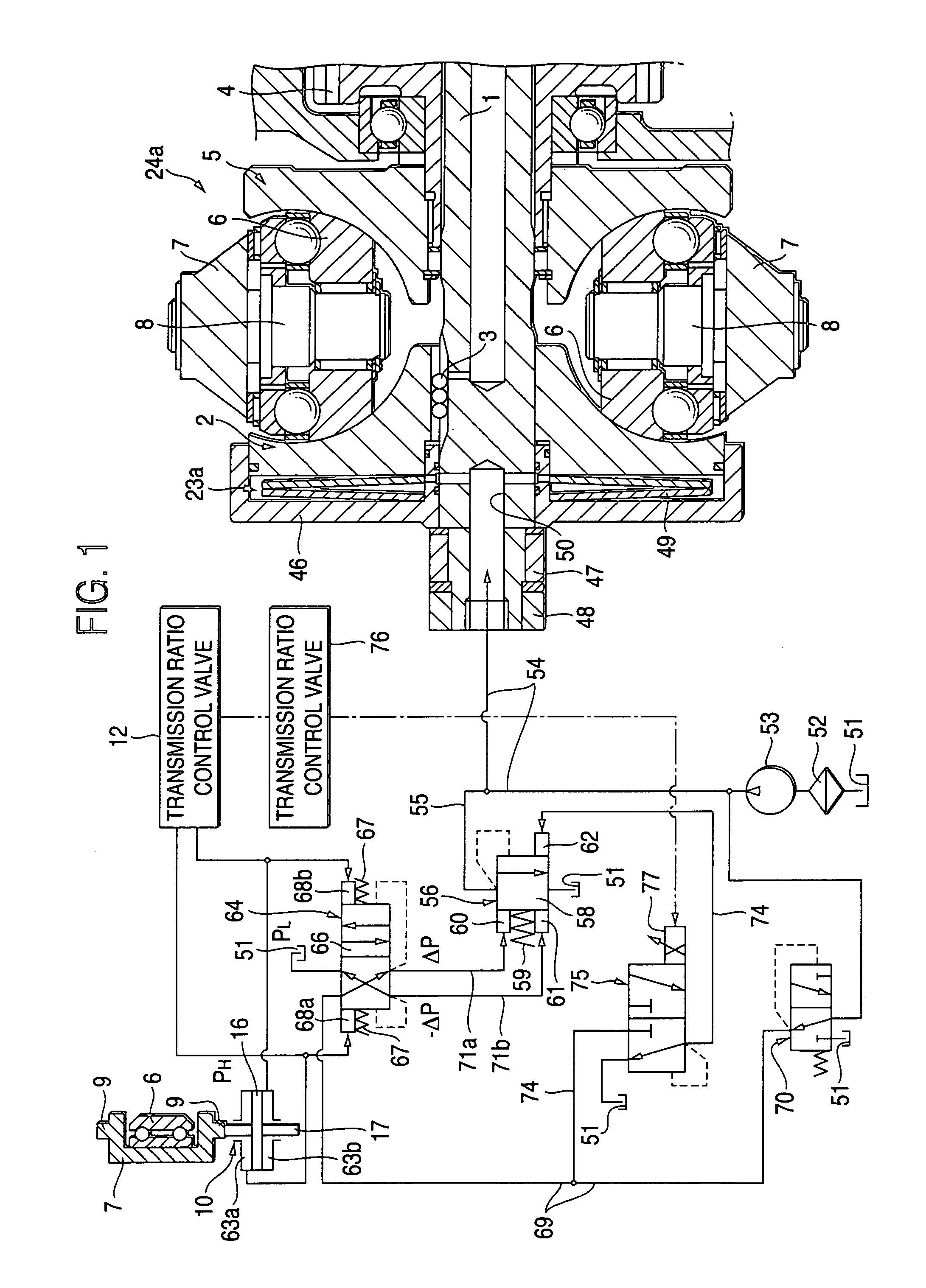
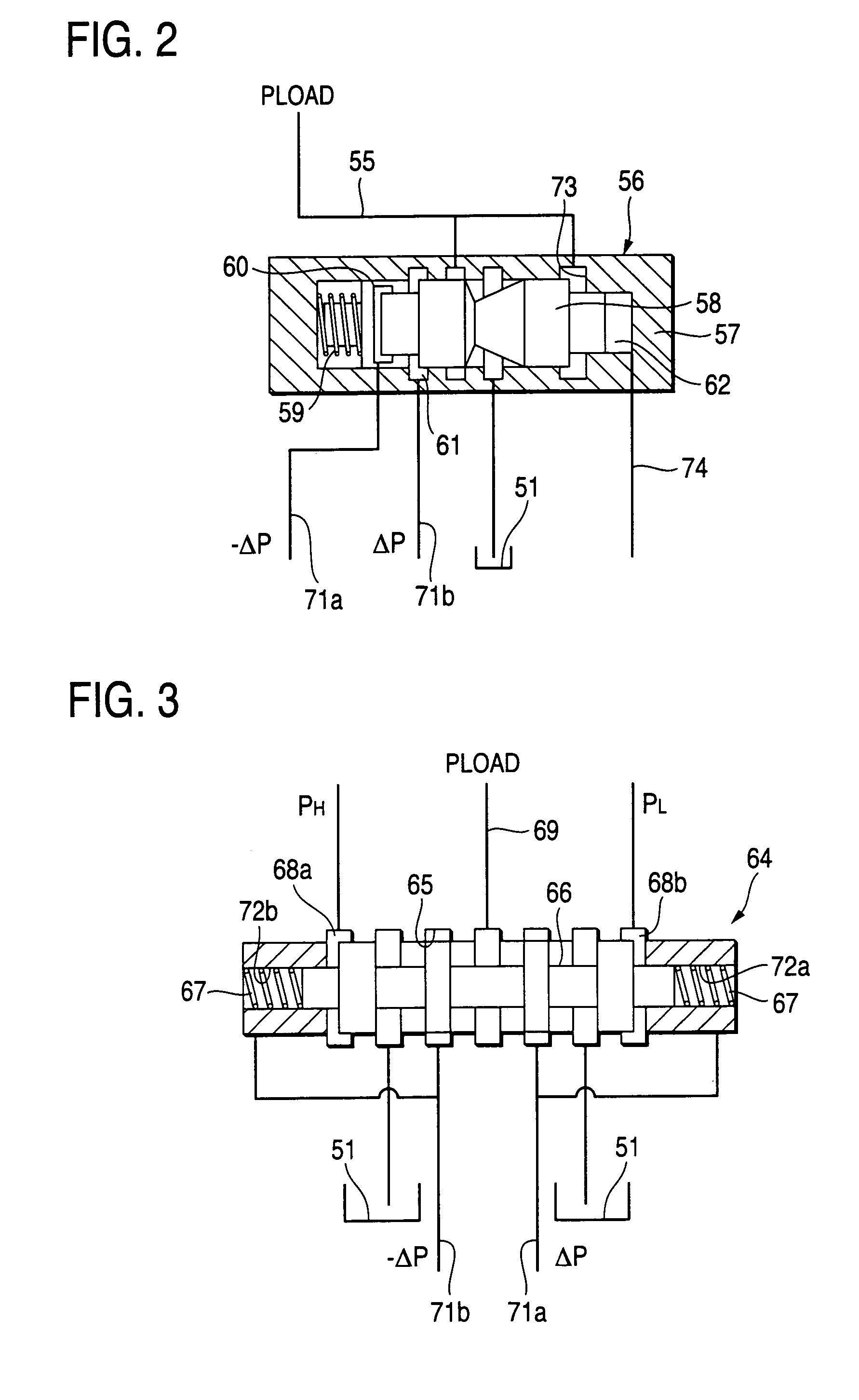
[0050]Now, FIGS. 1 to 3 show an embodiment of a toroidal-type continuously variable transmission according to the invention. By the way, the invention is characterized by the structure of such portion of the toroidal-type continuously variable transmission that can set proper the surface pressures of the rolling contact portions between the inner surfaces of input side and output side disks, 2, 5 and the peripheral surfaces of power rollers 6, 6, that is, the traction portions. The structure of a toroidal-type continuously variable transmission 24a itself is similar to the first example of the conventional structures shown in the previously described FIGS. 4 to 6 except that, as a pressing device 23a, there is used a pressing device of an oil pressure type. Therefore, illustration and description of the equivalent parts are omitted or simplified here. Thus, description will be given mainly of the characteristic portions of the invention. By the way, in FIG. 1, the oil pressure trans...


PUM


Abstract

A toroidal-type continuously variable transmission, has first and second disks respectively including inner surfaces; power rollers interposed for transmitting power; a pressing device for pressing the first disk toward the second disk; a main oil pressure control unit for non-electrically detecting the power for setting, as a target value, an oil pressure necessary for the pressing device when a transmission ratio between the first and second disks is a transmission ratio requiring a maximum pressing force, and increase the target value as the pressing force increases; an oil pressure correcting apparatus for electrically finding a necessary value of the oil pressure, the necessary value corresponding to the optimum value of pressing force generated by the pressing device, and also for introducing an oil pressure of a value into the pressing device, the oil pressure of the value being obtained by subtracting a correction value from the target value.

Description

BACKGROUND OF THE INVENTION[0001]1. Field of the Invention[0002]A toroidal-type continuously variable transmission according to the invention is used as transmission unit constituting an automatic transmission for a car, or, as a transmission apparatus for adjusting the operating speed of various industrial machines such as a pump.[0003]2. Description of the Related Art[0004]Conventionally, to use such a toroidal-type continuously variation transmission as shown in FIGS. 4 to 6 as an automatic transmission apparatus for a car has been studied and such use has been enforced in part of the car industry. A toroidal-type continuously variable transmission of this type is referred to as a toroidal-type continuously variable transmission of a double cavity type, in which input side disks 2, 2 serving as first disks are supported through their respective ball splines 3, 3 on the peripheries of the two end portions of an input shaft 1. Therefore, these two input side disks 2, 2 are supporte...

Claims


Application Information

Patent Timeline
Patent Type & Authority Patents(United States)
IPC IPC(8): F16H15/38F16H37/08F16H61/662
CPCF16H37/086F16H61/6649F16H2037/0886
Inventor IMANISHI, TAKASHIINOUE, EIJI
Owner NSK LTD
Why Eureka
Try Eureka