Implant surgery drill

a technology for implants and drills, applied in the field of implants surgery drills, can solve the problems of nut parts being all the connecting parts need to be replaced, and the nut part is more likely to wear, so as to ensure the durability and lifespan of the connecting parts, and precise perforation

Pending Publication Date: 2022-06-09
DMAX
View PDF0 Cites 0 Cited by
  • Summary
  • Abstract
  • Description
  • Claims
  • Application Information

AI Technical Summary

Benefits of technology

[0016]According to the present invention including the configuration as described above, as the integration is achieved by fastening a screw thread between a coupling hole provided on the bottom surface of the cutting part and a coupling protrusion provided on the upper surface of the connecting part, the abrasion of the coupling protrusion due to assembling and disassembling in a repetitive replacement may be actively reduced to secure the durability and lifespan of the connecting part.
[0017]According to the present invention, latch protrusions and holding protrusions are further provided between a coupling hole and a coupling protrusion so that protection is given for decoupling due to a mutual cross-latching.
[0018]According to the present invention, the cutting part is formed by a combination of at least one coupling part protruding downward from the bottom surface of the cutting part and a coupling hole formed in the stepped part and a fixing nut that passes through the coupling hole and a portion of the coupling part exposed to the bottom surface of the stepped part. As the coupling force between the connecting parts is reinforced, and the precise perforation may stably performed, so that an advantage of creating a more comfortable implant environment is expected.

Problems solved by technology

In order to safely and precisely implant the patient's alveolar bone, the method is carried out by gradually expanding a perforation of small diameter while varying the size of the drill, and the above-mentioned prior art has to abide the inconvenience of separating both the connecting part and the cutting part from each other in the handpiece, furthermore, there has been a problem that all the connecting parts, which are configured integrally when the cutting part is replaced due to wear, have to be replaced.
Further, in general, a nut part is more likely to wear due to weaker durability thereof compared to a bolt part, wherein the durability of the connecting part is subjected to a serious wear while a plurality of cutting part are replaced and used in one connecting part.
In addition, the cutting part also induces to replacement use for a certain period of time due to wear while cutting the alveolar bone and hygiene and maintenance problems due to the intricate configuration, and an economic burden on use has emerged.

Method used


Image

  • Implant surgery drill
  • Implant surgery drill
  • Implant surgery drill

Examples


Embodiment Construction

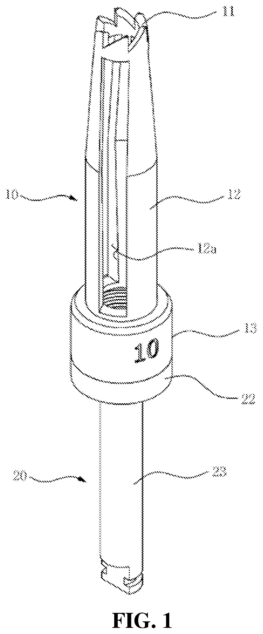
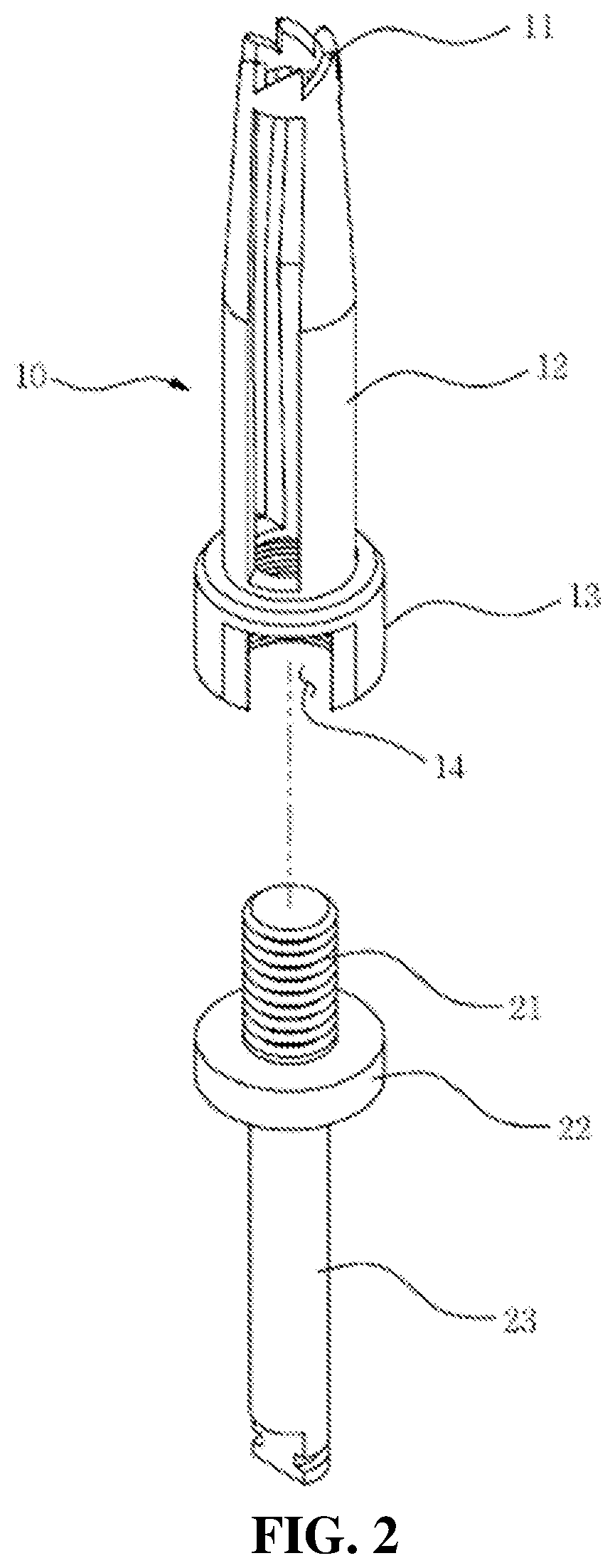
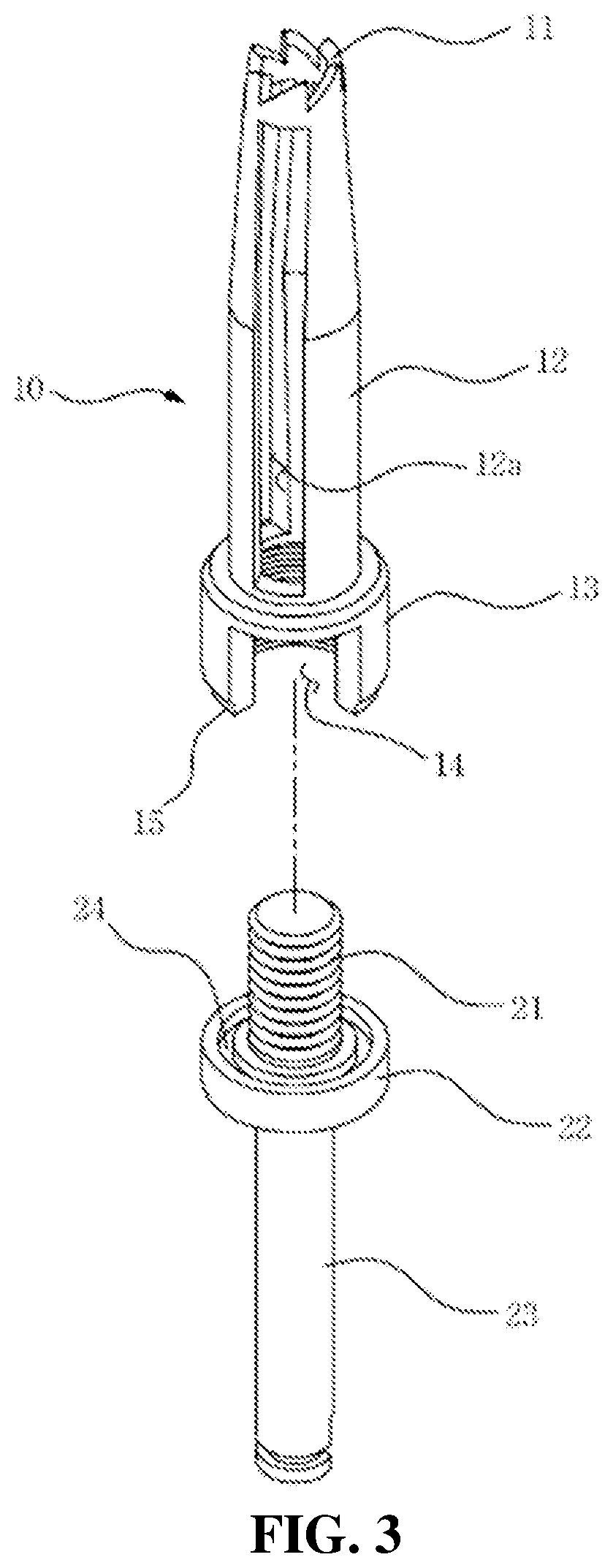
[0025]Hereinafter, a configuration, operations, and effects of the present invention will be disclosed with reference to the attached drawings.

[0026]Objects, characteristics and advantages of the present invention will be more clearly understood from the detailed description as will be described below and the attached drawings. Before the present invention is disclosed and described, it is to be understood that the disclosed embodiments are merely exemplary of the invention, which can be embodied in various forms. Therefore, specific structural and functional details disclosed herein are not to be interpreted as limiting, but merely as a basis for the claims and as a representative basis for teaching one of ordinary skill in the art to variously employ the present invention in virtually any appropriately detailed structure. The corresponding parts in the embodiments of the present invention are indicated by corresponding reference numerals.

[0027]The present invention relates to a su...


PUM


Abstract

An implant surgery drill capable of preventing accidents in advance by actively reinforcing coupling force between a cutting part for cutting the alveolar bone and a connecting part for connecting the cutting part to a handpiece is proposed. The drill can include a cutting part having a plurality of cutting blades that comprise saw teeth and are aligned in a circular shape so as to perforate the alveolar bone; and a connecting part interposed between the handpiece and the cutting part, wherein, specifically, the cutting part including: the saw teeth aligned in a circular shape at the upper end thereof; a cutting upper part extending downward from the saw teeth; and a cutting lower part protruding downward from the cutting upper part with an expanded diameter.

Description

TECHNICAL FIELD[0001]The present invention relates to a surgery drill for dental implant capable of perforate grooves in an alveolar bone, specifically, to prevent accidents in advance by actively reinforcing coupling force between a cutting part for cutting the alveolar bone and a connecting part for connecting the cutting part to a handpiece.BACKGROUND ART[0002]In general, implant surgery is a dental treatment technique in which a biocompatible implant body is implanted in positions where there is loss of extraction, so as to restore the function of the natural teeth. The method for implanting an implant body may be classified according to implant positions such as endosseous implant, submucosal implant, bone penetrating type implant, and endodontic implant, and recently, a method of using a handpiece after forming a perforation in an alveolar bone and coupling a thread-type implant is often used.[0003]Meanwhile, since an implant type may be determined according to diameter, depth...

Claims


Application Information

Patent Timeline
Patent Type & Authority Applications(United States)
IPC IPC(8): A61C1/14A61C8/00A61B17/16
CPCA61C1/14A61C8/0089A61B17/1673A61B17/1637A61B17/1617A61B17/1615A61B17/1655A61C1/08
Inventor PARK, TAE SEOK
Owner DMAX
Why Eureka
Try Eureka