USB connector and its fabrication method

Active Publication Date: 2010-05-06
CHANT SINCERE
View PDF10 Cites 23 Cited by
  • Summary
  • Abstract
  • Description
  • Claims
  • Application Information

AI Technical Summary

Benefits of technology

[0009]The present invention has been accomplished under the circumstances in view. It is one object of the present invention to provide a USB connector fabrication method, which eliminates the problem of creating two different dies for making two differen

Problems solved by technology

Nowadays, these data transmission speeds cannot satisfy the demand for quick transmission of a big amount of data within a limited time.
The aforesaid conventional USB 3.0 connector fabrication method has drawbacks as follows:1. Two separate stamping dies are needed for stamping two metal sheets into tw

Method used


Image

  • USB connector and its fabrication method
  • USB connector and its fabrication method
  • USB connector and its fabrication method

Examples


Example

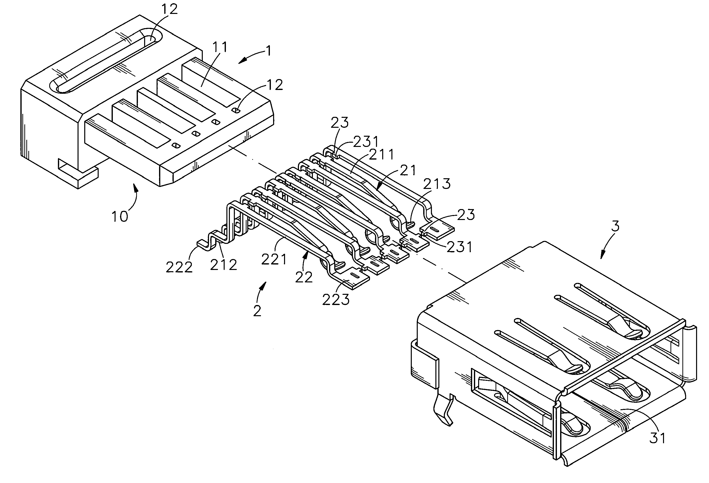
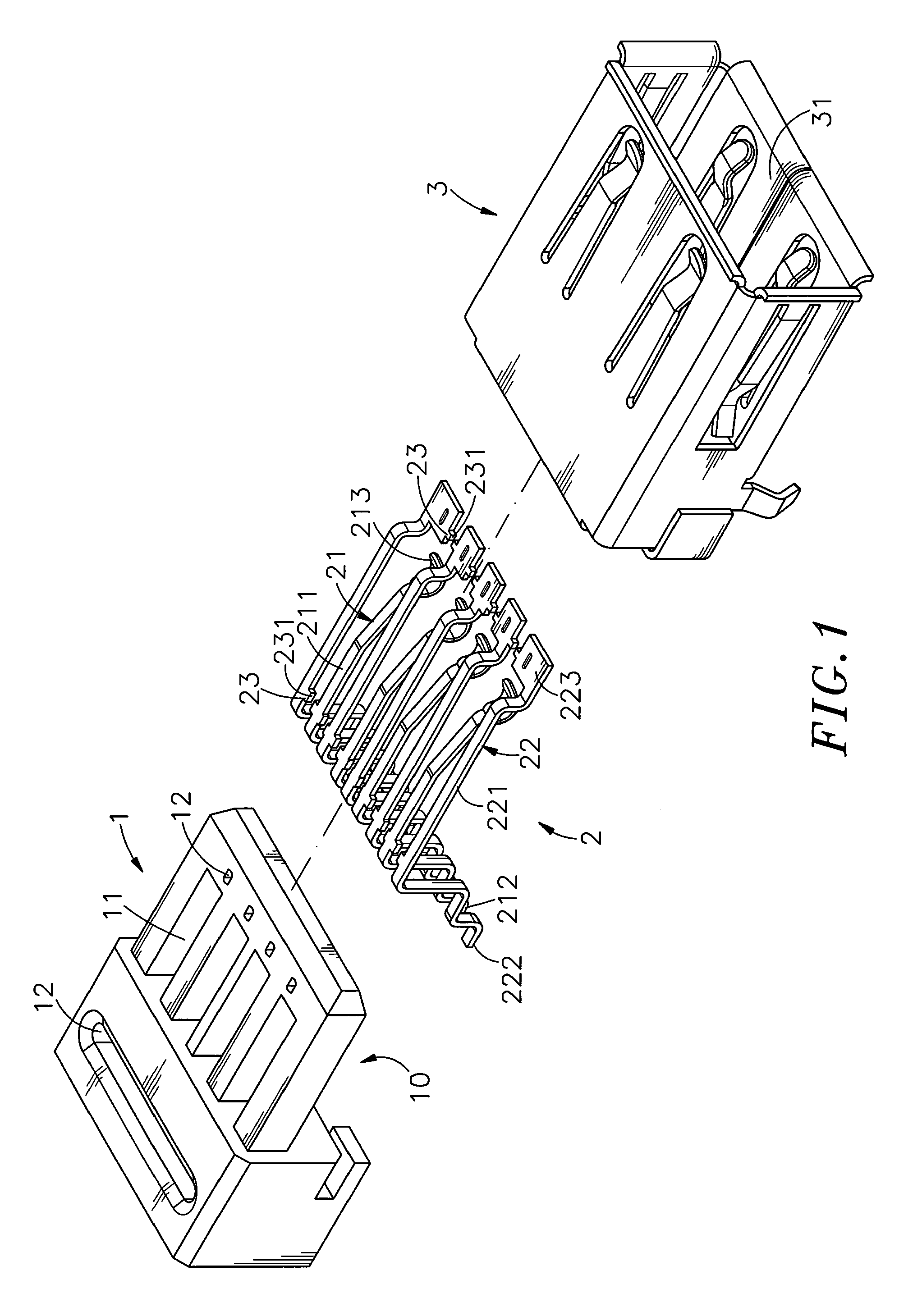
[0026]Referring to FIG. 1 and FIG. 6, a USB (universal serial bus) connector in accordance with a first embodiment of the present invention is shown comprising an electrically insulative housing 1, a terminal set 2 and a metal shield 3.

[0027]The electrically insulative housing 1 defines a receiving space 10, a plurality of suspension slots 11 arranged in a parallel manner in communication with the receiving space 10 and a plurality of punch holes 12 arranged at front and rear sides relative to the suspension slots 11.

[0028]The terminal set 2 is mounted in the electrically insulative housing 1, comprising a set of first terminals 21, a set of second terminals 22 and a plurality of material bridges 23 joining the first terminals 21 and the second terminals 22. The first terminals 21 and the second terminals 22 are alternatively arranged in a row and connected to one another by the material bridges 23, each having a narrow elongated base portion 211 or 221, a rear bonding end portion 2...


PUM

PropertyMeasurementUnit
Shapeaaaaaaaaaa

Abstract

A USB connector fabrication method includes the steps of (a) stamping a metal sheet into a terminal set having a set of first terminals, a set of second terminals and material bridges joining the first terminals and the second terminals, (b) preparing an electrically insulative housing having punch holes and then mounting the terminal set in the electrically insulative housing to keep the material bridges in vertical alignment with the punch holes, (c) using a machine to cut off the material bridges and (d) securing a metal shield around the periphery of the electrically insulative housing.

Description

BACKGROUND OF THE INVENTION[0001]1. Field of the Invention[0002]The present invention relates to USB connector fabrication technology and more particularly, to a USB connector fabrication method, which simplifies USB manufacturing process and facilitates installation, saving much fabrication time and installation cost.[0003]2. Description of the Related Art[0004]Following fast development of modern technology, many different advanced electronic devices have been intensively used in our daily life. Further, different transmission cables are used for data transmission among different electronic devices. Serial transmission connectors, such as USB (Universal Serial Bus) 1.1 and 2.0, are intensively used in different electronic devices to provide transmission speeds 1.5 Mbit / s and 480 Mbit / s respectively. Nowadays, these data transmission speeds cannot satisfy the demand for quick transmission of a big amount of data within a limited time. In consequence, high speed data transmission co...

Claims


Application Information

Patent Timeline
IPC IPC(8): H01R13/648H01R43/20
CPCH01R13/65802H01R43/16Y10S439/937Y10T29/49208H01R13/6582
Inventor CHIU, WEN-TAYEN, MING-HUILAI, CHUN-MINGLIN, YEH-HSI
Owner CHANT SINCERE
Why Eureka
Try Eureka