Electromagnetic imaging apparatus and manufacturing method therefor

Active Publication Date: 2005-09-27
SHIMADZU CORP +1
View PDF6 Cites 14 Cited by
  • Summary
  • Abstract
  • Description
  • Claims
  • Application Information

AI Technical Summary

Benefits of technology

[0014]This invention has been made having regard to the state of the art noted above, and has for a primary object to provide an electromagnetic imaging apparatus a

Problems solved by technology

As a result, its thickness tends to vary, making it difficult to level out the surface over large areas.
Further, a high degree of precision is required in adjusting a re

Method used


Image

  • Electromagnetic imaging apparatus and manufacturing method therefor
  • Electromagnetic imaging apparatus and manufacturing method therefor
  • Electromagnetic imaging apparatus and manufacturing method therefor

Examples


Example

[0062]Preferred embodiments of the present invention will be described in detail hereinafter with reference to the drawings.

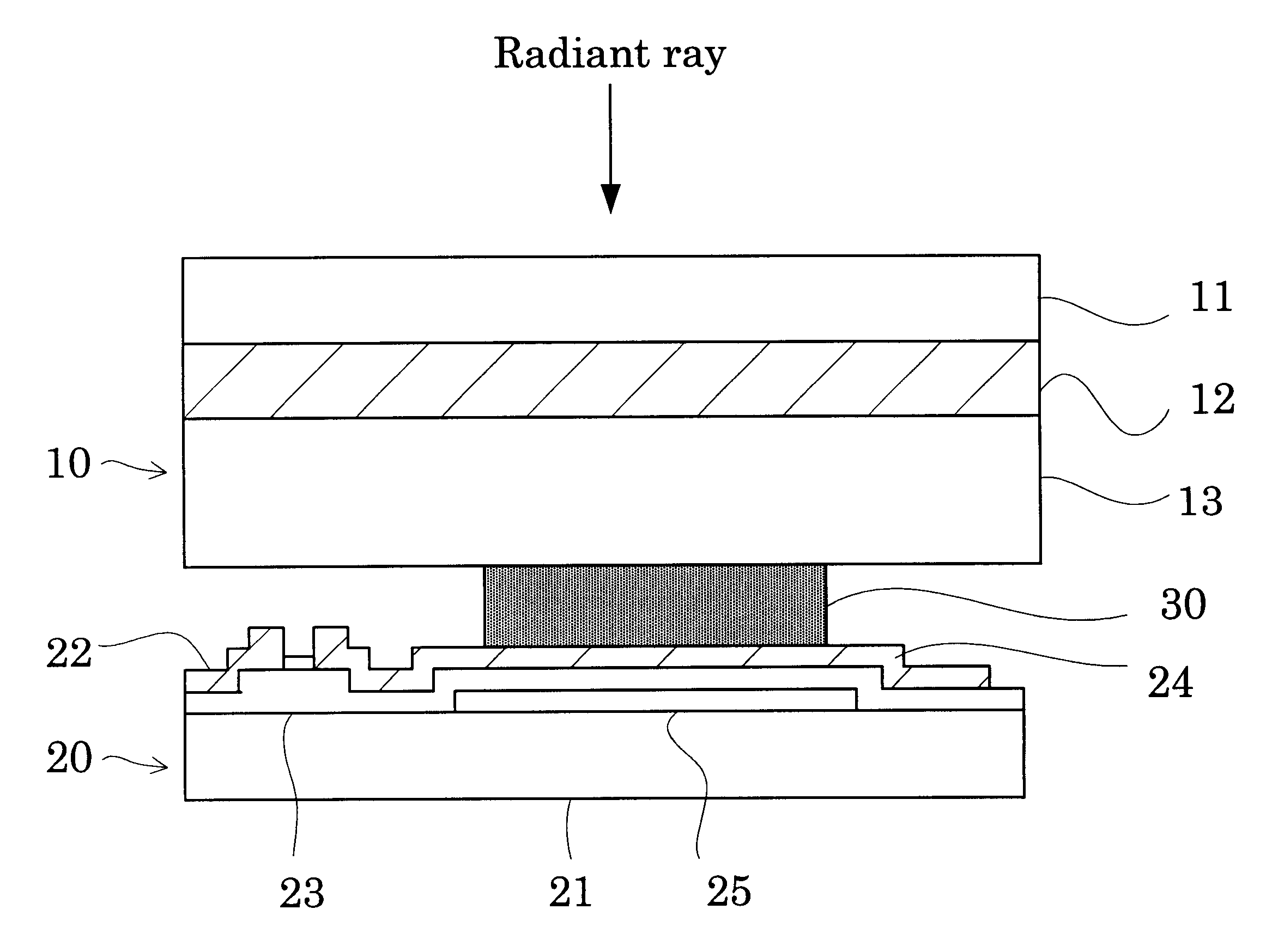
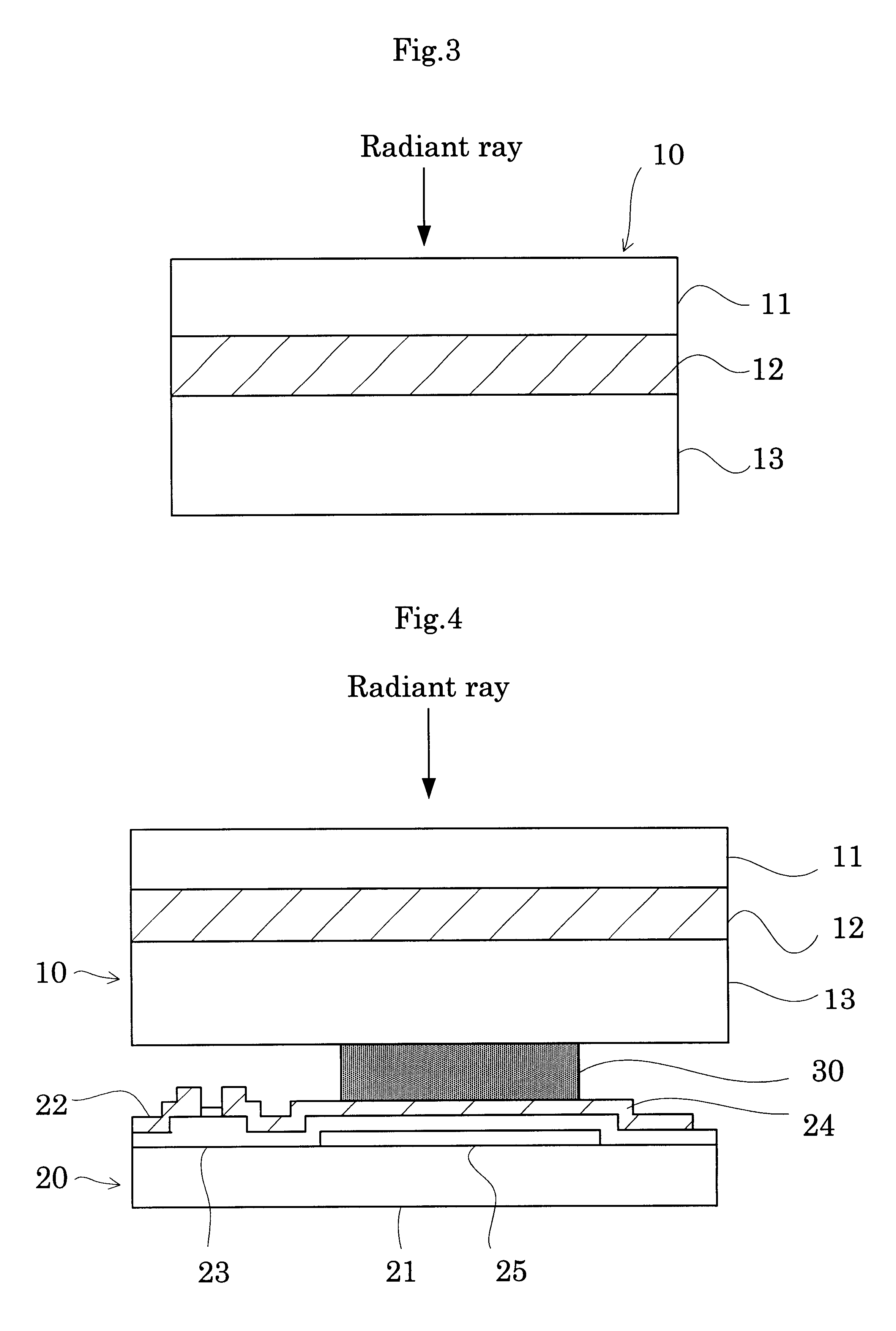
[0063]FIG. 3 is a sectional view showing a detector panel used in an electromagnetic imaging apparatus according to this invention for detecting electromagnetic radiation. FIG. 4 is a sectional view of the detector panel and a readout panel joined together. For expediency of illustration, FIG. 4 shows only a fragment corresponding to one pixel.

[0064]The electromagnetic imaging apparatus in this embodiment, broadly, includes a detector panel 10 for generating carriers, which are electron-hole pairs, in response to incident radiation, and a readout panel (hereinafter referred to as “active matrix panel”) 20 for reading charges generated in the detector panel 10. The detector panel 10 and active matrix panel 20 are joined and electrically connected together through an electroconductive resin 30. The electroconductive resin 30 corresponds to the electroconductive m...


PUM


Abstract

A detector panel having a bias application electrode and a converter layer formed on a supporting substrate, and a readout panel (active matrix panel), are bonded to each other directly through a single layer of electroconductive resin. That is, a pattern of photosensitive resin is formed before-hand on reading electrodes of the readout panel, and this readout panel and the converter layer are bonded together directly. Since the converter layer has no pixel electrodes formed thereon, the converter layer need not be smoothed, and the two panels need not be positionally adjusted to each other with high precision.

Description

BACKGROUND OF THE INVENTION[0001](1) Field of the Invention[0002]This invention relates to an electromagnetic imaging apparatus for use in the medical and industrial fields to detect electromagnetic waves such as light and other radiation, and to a method of manufacturing such apparatus. More particularly, the invention relates to a technique for depositing and joining a detector panel for detecting electromagnetic radiation and a readout panel for reading, from the detector panel, carriers which are electron-hole pairs generated as a result of detection of the electromagnetic radiation.[0003](2) Description of the Related Art[0004]A construction of a conventional electromagnetic imaging apparatus will be described with reference to FIGS. 1 and 2.[0005]FIG. 1 is a sectional view showing a detector panel for detecting electromagnetic radiation. FIG. 2 is a sectional view of the detector panel and a readout panel joined together. For expediency of illustration, FIG. 1 shows only a fra...

Claims


Application Information

Patent Timeline
IPC IPC(8): G01J5/20G01J5/22G01T1/24G01T1/00H01L27/146H01L27/14H01L31/08H01L31/09H04N5/32H04N5/335H04N5/369
CPCH01L27/14609H01L27/14634H01L27/1469
Inventor TOKUDA, SATOSHIYOSHIMUTA, TOSHINORIIZUMI, YOSHIHIROTERANUMA, OSAMU
Owner SHIMADZU CORP
Why Eureka
Try Eureka