Aircraft Landing Gear Loader

Inactive Publication Date: 2010-05-13
THE BOEING CO
View PDF4 Cites 18 Cited by
  • Summary
  • Abstract
  • Description
  • Claims
  • Application Information

AI Technical Summary

Benefits of technology

[0008]In accordance with the exemplary embodiments thereof described herein, the present disclosure provides a method and apparatus for loading the MLG of a large aircraft into or from the wheel wells

Problems solved by technology

Moreover, repairs or maintenance of large aircraft in the field often must be effected in an actual “flight line” environment, necessitating the removal and installation of large MLG at heights of up to 154 inches above the tarmac, and additionally, in a potentially more hazardous environment, e.g., an Underwriters Laboratories (“UL”) “Class 1, Division 1” (fueled aircraft) environment.
However, it should be noted that the 747 MLG loader is not capable of supporting the increased weight of the larger MLG of more recent aircraft, e.g., the Boeing 777, and is therefore incapable of installing the 777 MLG in either a moving line or a flight line environment.
The disadvant

Method used


Image

  • Aircraft Landing Gear Loader
  • Aircraft Landing Gear Loader
  • Aircraft Landing Gear Loader

Examples


Embodiment Construction

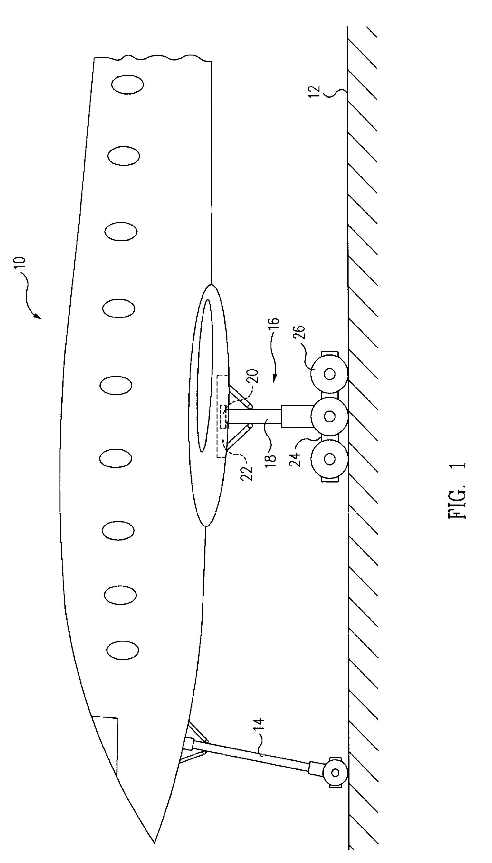
[0027]FIG. 1 is a left side partial elevation view of a large aircraft 10 situated on a generally horizontal surface, such as a hangar floor or tarmac 12, and supported thereon by a nose gear 14 and a left main landing gear (“MLG”) 16 of the aircraft. In the particular embodiment of aircraft 10 and MLG 16 illustrated, the MLG comprises an elongated strut 18 having an upper end 20 extending into a wheel well 22 of the aircraft, where it is coupled to associated structure adapted to support the aircraft on the MLG and to extend the MLG from and retract it completely into the wheel well during takeoff, flight and landing operations. The MLG 16 typically further includes a truck 24 having a plurality of wheels 26 rotatably mounted thereon. In a typical embodiment, the MLG 16 may include six wheels, can weigh more than 7 tons, and measure more than 154 inches in length.

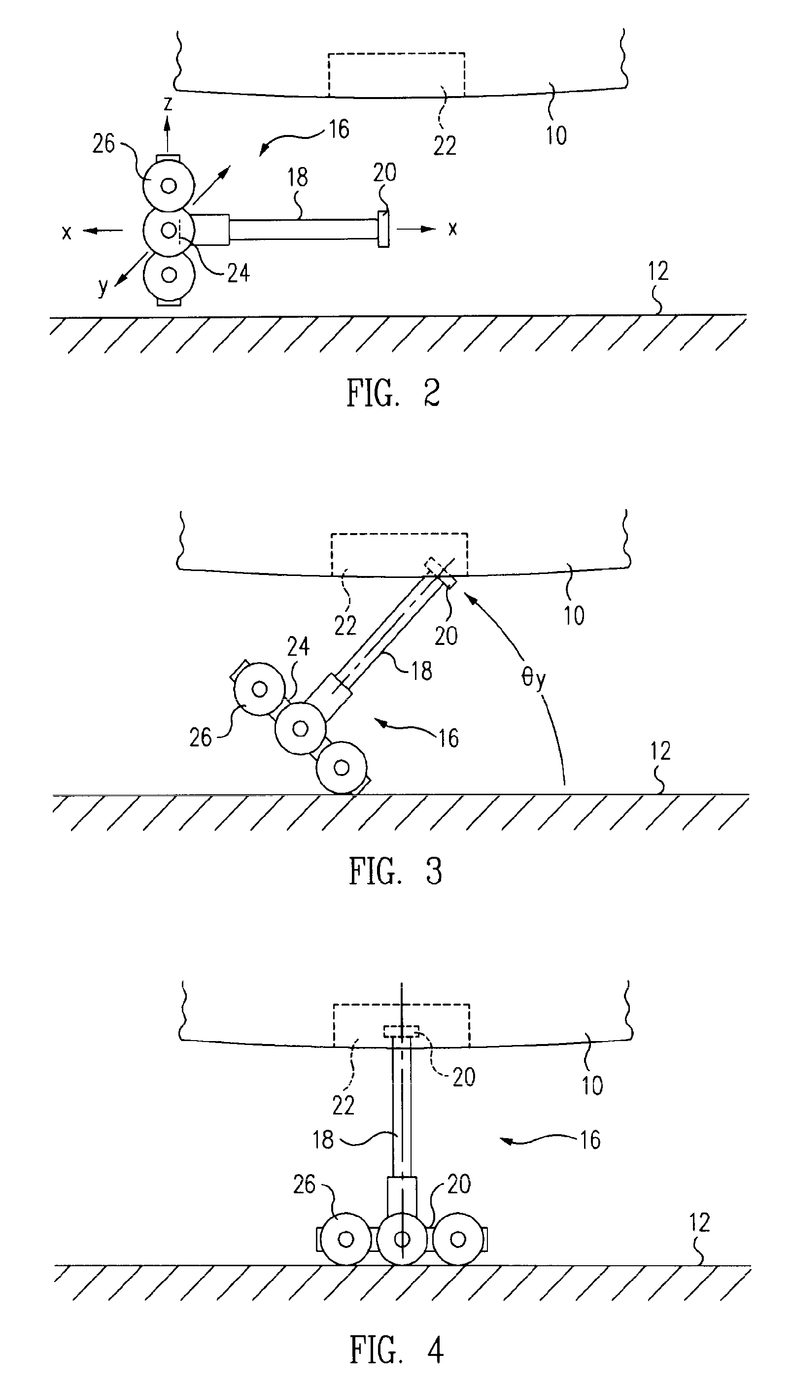
[0028]FIGS. 2-4 schematically illustrate the sequential steps involved in one method of loading, i.e., installing, the M...


PUM


Abstract

An apparatus for loading and unloading a main landing gear (“MLG”) of an aircraft includes a fixture that is adapted to couple to a truck of the MLG such that a sagittal plane of the fixture is parallel to or coplanar with a sagittal plane of the MLG and both translational forces and turning moments applied to the fixture are coupled directly through the fixture to the MLG, a mechanism for controllably translating the fixture in the sagittal plane thereof, and a mechanism for controllably rotating the fixture in the sagittal plane thereof.

Description

RELATED APPLICATIONS[0001]This application is a continuation-in-part of U.S. application Ser. No. 11 / 274,036, filed Nov. 15, 2005.TECHNICAL FIELD[0002]This disclosure pertains to mechanisms for lifting and manipulating heavy objects in general, and more particularly, to a loader for the main landing gear of a large aircraft.BACKGROUND[0003]Modern large aircraft, such as the Boeing 777, are typically assembled on a moving assembly line. Moving line assembly requires that the aircraft's main landing gear (MLG), each of which may weigh more 14,000 lbs., be installed while the weight of the aircraft is supported on jacks, with the belly of its fuselage disposed 106 inches or more above the floor. Moreover, repairs or maintenance of large aircraft in the field often must be effected in an actual “flight line” environment, necessitating the removal and installation of large MLG at heights of up to 154 inches above the tarmac, and additionally, in a potentially more hazardous environment, ...

Claims


Application Information

Patent Timeline
IPC IPC(8): B64F5/00B66F1/00
CPCB64F5/0036B66F7/22B66F7/14B64F5/50
Inventor GROVES, OLIVER J.HEILMAN, GARY F.HARRISON, CHARLES D.TAYLOR, BART M.CHUN, SE Y.KIM, TAE H.KOYFMAN, GREGORYOARE, EDWARD D.VIRING, JACOB D.KONEN, MICHAEL H.
Owner THE BOEING CO
Why Eureka
Try Eureka