

Split ring retainer for turbine outer air seal
- Summary
- Abstract
- Description
- Claims
- Application Information
AI Technical Summary
Benefits of technology
Problems solved by technology
Method used
Image

Examples
Embodiment Construction
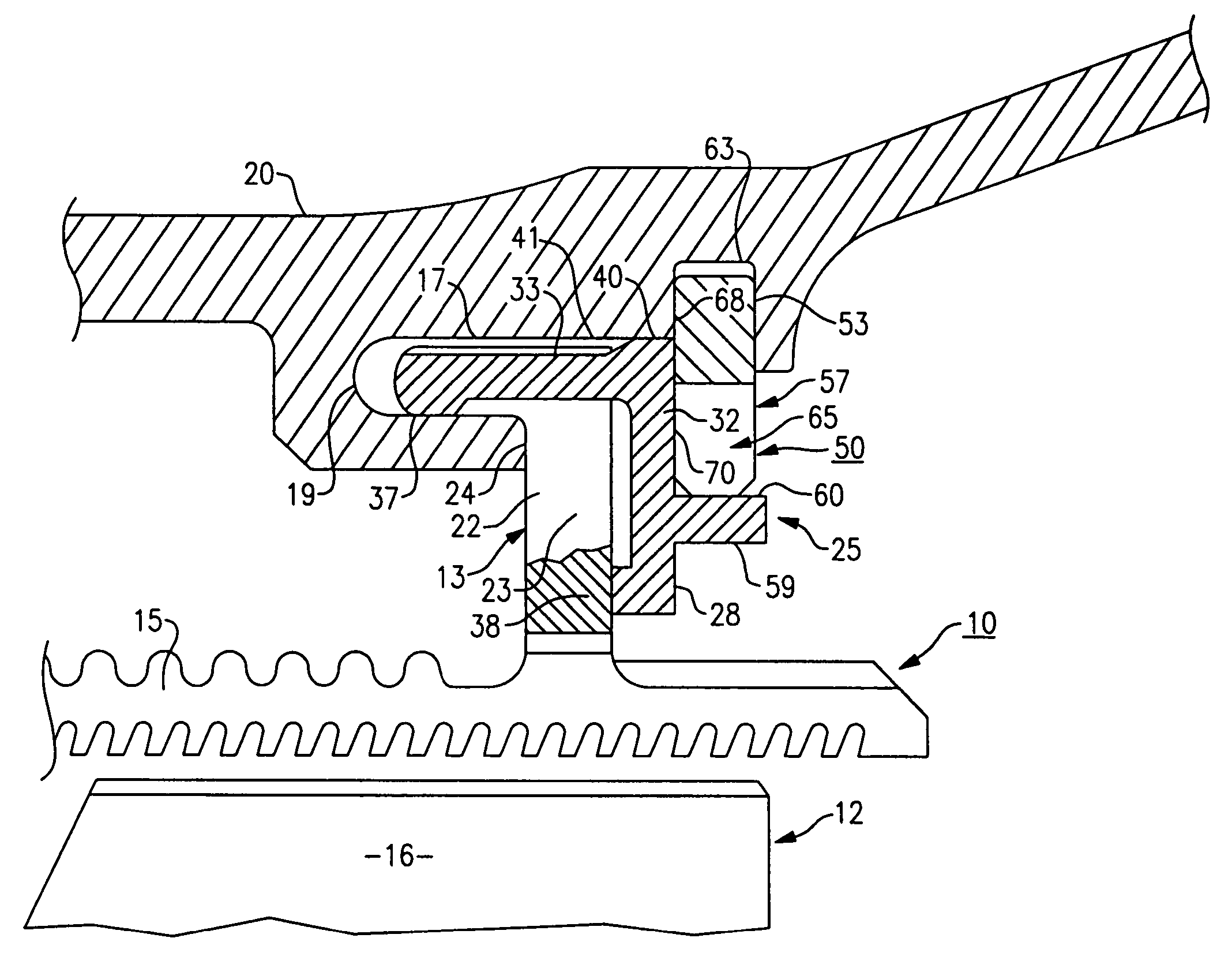
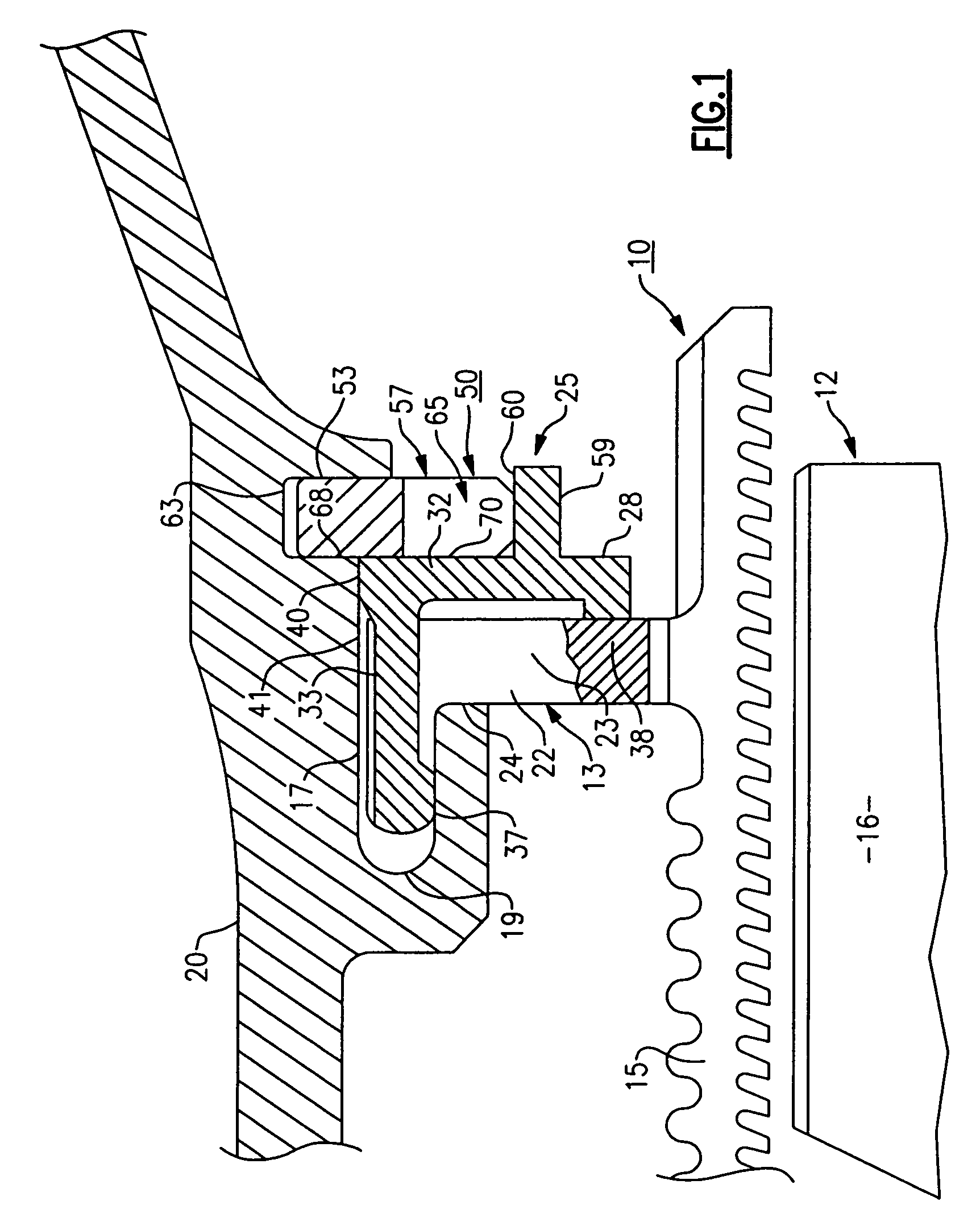
[0024] Referring initially to the drawings, there is illustrated a partial side elevation in section in FIG. 1 showing an annular outer air seal assembly 10 of a turbine rotor stage 12. The seal assembly contains a circular hook-shaped hanger 13 for locating the air seal 15 around the top edges of the blades 16 of the rotor stage. The hanger contains an annular flange 17 that is received within an axially disposed annular groove 19 formed in the turbine casing 20.
[0025] The air seal is connected to the annular flange 17 by means of a radially disposed arm 22. One side wall 23 of the arm bears against a radially disposed surface 24 located on the casing to register the air seal in assembly. A locking mechanism, generally referenced 25, serves to secure the air seal in a locked and registered position as illustrated in FIG. 1. The locking mechanism includes a plurality of arcuate-shaped key segments 28. Each key segment includes a radially disposed arcuate-shaped panel 32 having one ...
PUM
 Abstract
Description
Claims
Application Information