Cabinet of electrical apparatus and antenna apparatus

Active Publication Date: 2010-06-10
MITSUMI ELECTRIC CO LTD
View PDF5 Cites 6 Cited by
  • Summary
  • Abstract
  • Description
  • Claims
  • Application Information

AI Technical Summary

Benefits of technology

[0009]It is, therefore, a main object of the present invention to maintain waterproof and airproof performance of both the hole where a fastening section such as a male screw penetrates through and the gap between the cover and the base.

Problems solved by technology

When the pad member deforms in this way, the force of the base being pulled toward the cover becomes weak.

Method used


Image

  • Cabinet of electrical apparatus and antenna apparatus
  • Cabinet of electrical apparatus and antenna apparatus
  • Cabinet of electrical apparatus and antenna apparatus

Examples


Embodiment Construction

[0032]The best mode for carrying out the cabinet of the electrical apparatus and the antenna apparatus according to the present invention will be explained in detail with reference to the drawings. However, the scope of the invention is not limited by the illustrated examples.

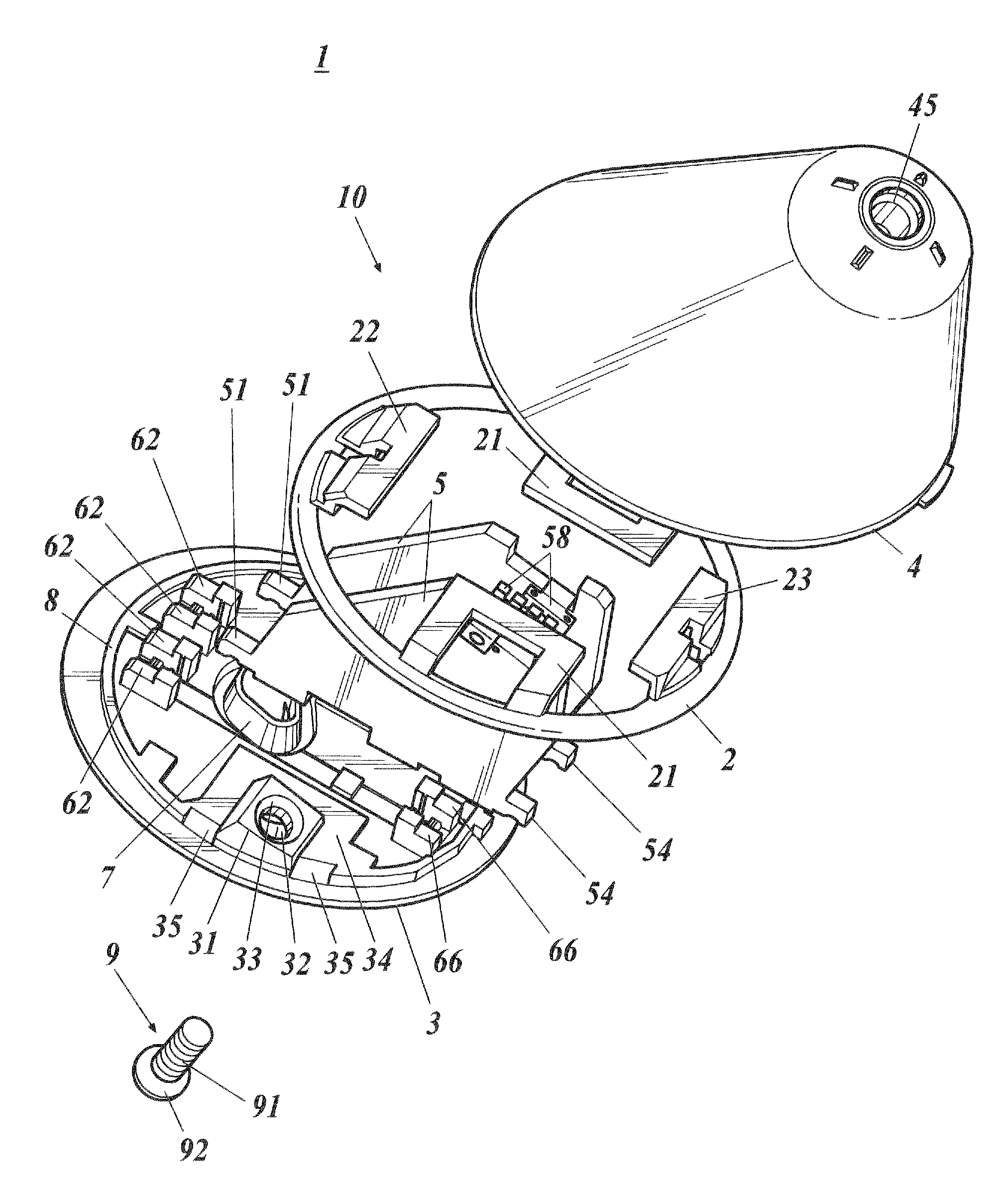
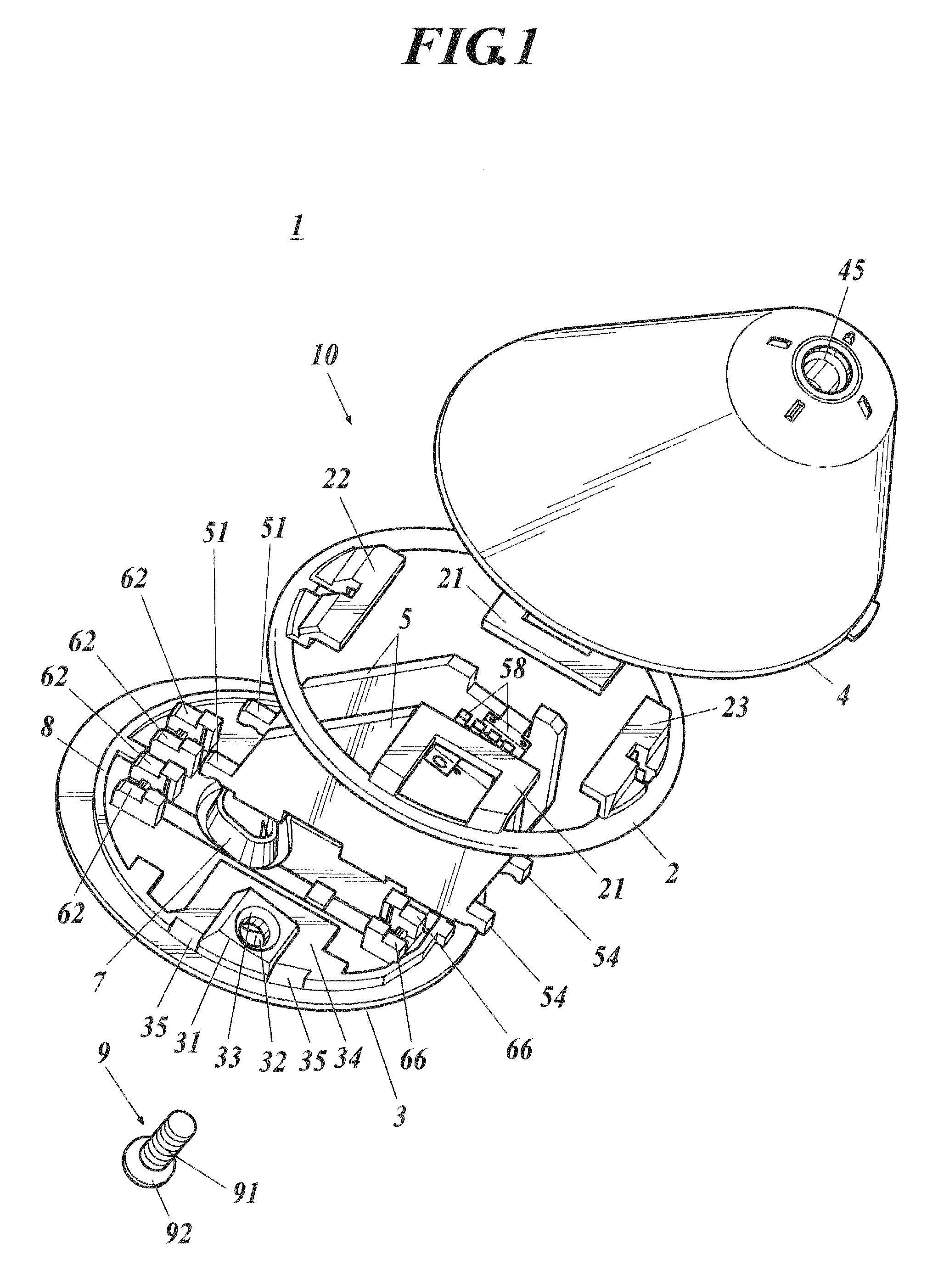
[0033]FIG. 1 is an exploded perspective view showing an antenna apparatus 1 from a view diagonally above, FIG. 2 is an exploded perspective view showing the antenna apparatus 1 from a view diagonally below, and FIG. 3 is a vertical cross-sectional view showing the antenna apparatus 1. The antenna apparatus 1 as an electrical apparatus is mounted on installing points such as a roof of an automobile, a roof of a vehicle, etc.

[0034]The antenna apparatus 1 includes a cabinet 10, and two circuit substrates 5, and these circuit substrates are accommodated in the cabinet 10. A branching circuit, amplifying circuit, etc. are included in the circuit substrate 5. One of the two circuit substrates 5 is an AM / FM substrate,...


PUM


Abstract

Disclosed is a cabinet of an electrical apparatus including: a base; a cover to cover over the base; a gasket placed on a top face of the base and nipped between a bottom edge section of the cover and the base; a fastening section to penetrate through the base from a bottom face to the top face of the base to connect to an inner face of the cover and to tighten so that the base is pulled to a cover side; a seal integrally formed with the gasket to surround on the top face of the base a through hole which the fastening section penetrates; and a hood provided on an inner face of the cover so as to surround a connecting portion of the fastening section and the cover, and the hood being pressed against the seal.

Description

BACKGROUND OF THE INVENTION[0001]1. Field of the Invention[0002]The present invention relates to a cabinet of an electrical apparatus and an antenna apparatus, and in particular, a cabinet with excellent waterproof and airproof performance and an antenna apparatus.[0003]2. Description of Related Art[0004]In an electrical apparatus such as an antenna apparatus, etc., a circuit substrate is accommodated inside a cabinet and a circuit substrate is supported inside the cabinet. As a cabinet, there is a cabinet where a base and a cover are set together, the base is provided in a plate-shape and the bottom of the cover is open to cover over the base so that the opening of the cover is closed by the base (for example, see Japanese Patent Application Laid-Open Publication No. 2005-102031).[0005]In order to fix the cover to the base, a screw linking section is used. In other words, a female screw is formed on the inside face of the cover and a through hole is formed on the base to pass a sha...

Claims


Application Information

Patent Timeline
IPC IPC(8): H01Q1/24A47B81/00
CPCH01Q1/42H01Q1/12
Inventor SATO, KYUICHISUZUKIKAMADA, KENICHIKATO, TAKAO
Owner MITSUMI ELECTRIC CO LTD
Why Eureka
Try Eureka