Swivel Castor Braking System

Active Publication Date: 2010-07-15
FALLSHAW HLDG
View PDF13 Cites 27 Cited by
  • Summary
  • Abstract
  • Description
  • Claims
  • Application Information

AI Technical Summary

Benefits of technology

[0008]Preferably, in the braking position the bo

Problems solved by technology

This will position two of the brake pedals underneath the trolley,

Method used


Image

  • Swivel Castor Braking System
  • Swivel Castor Braking System
  • Swivel Castor Braking System

Examples


Embodiment Construction

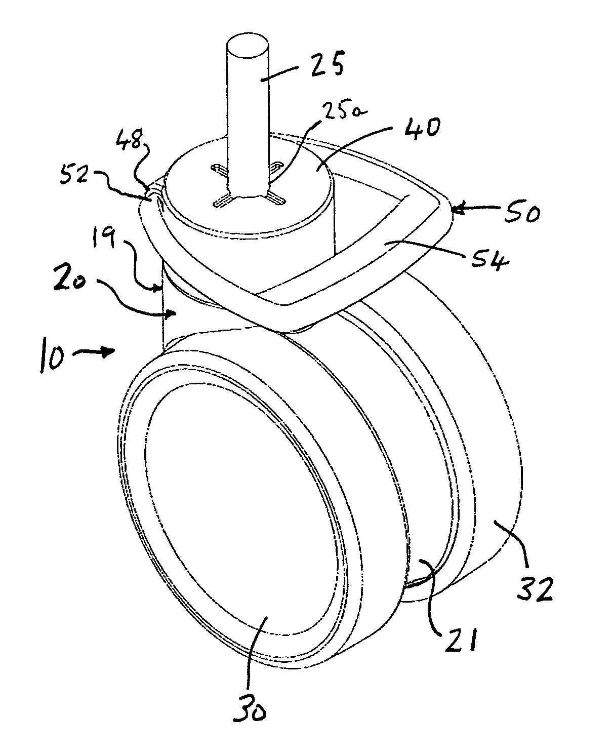
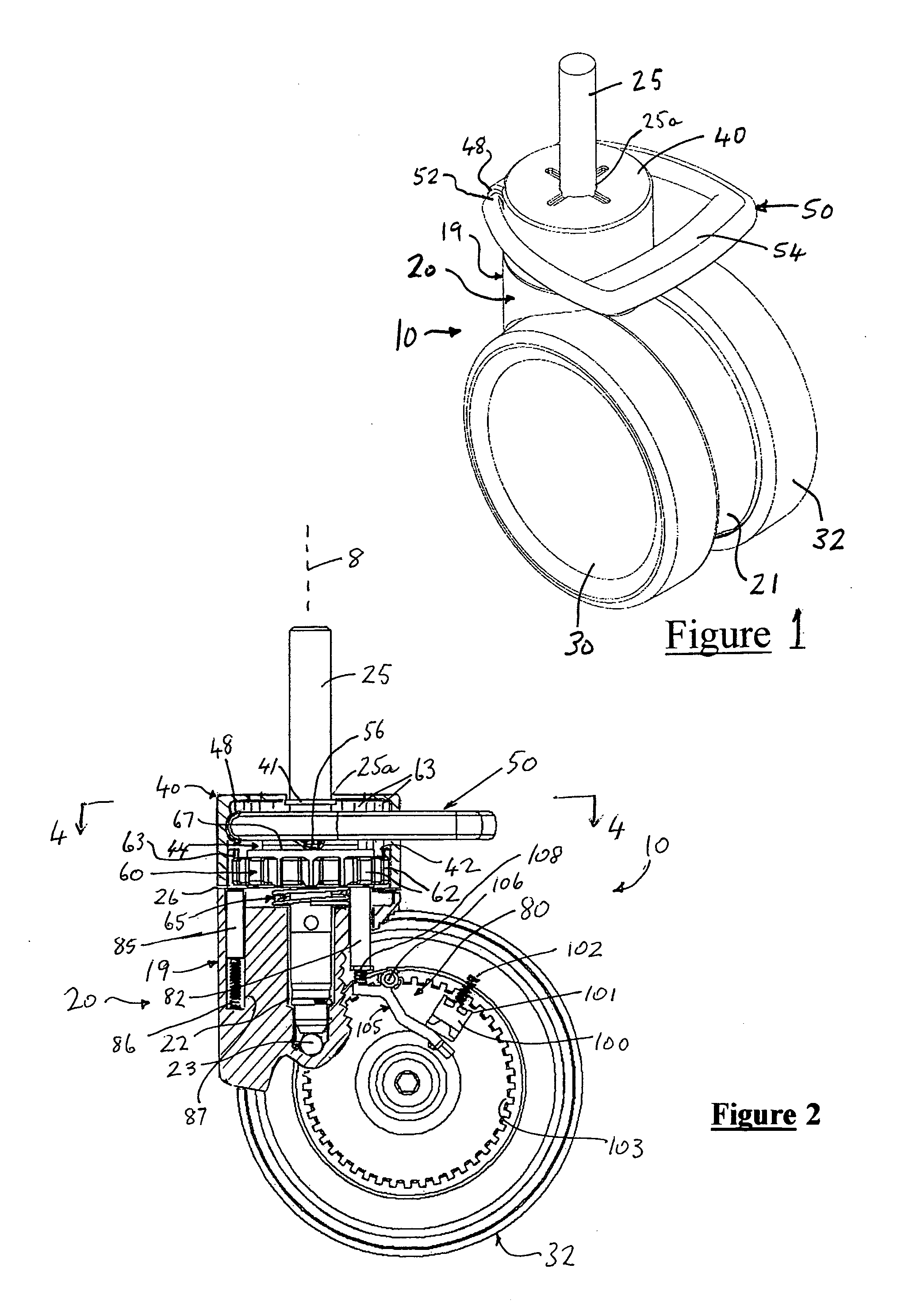
[0028]The illustrated swivel castor assembly 10 includes a main body 20 that journals a pair of rotatable wheels 30,32 engageable with a floor or ground surface below the body, and is in two principal parts: a bi-flanged disc portion 21 between the wheels that is truncated at its base to clear the underlying floor or ground surface, and a broader upstanding portion 19, of generally annular cross-section at its upper end, projecting eccentrically from the disc portion.

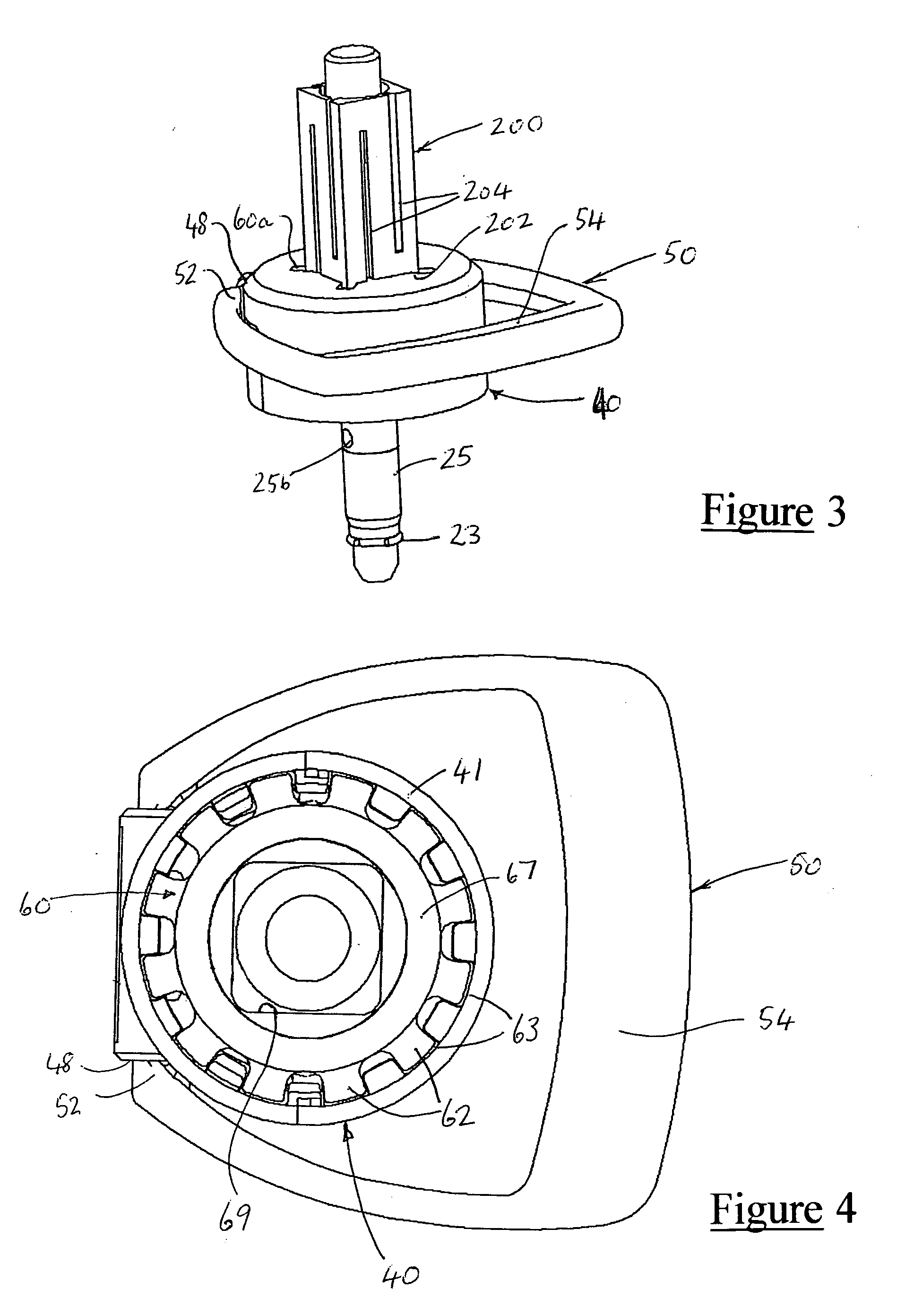
[0029]Upstanding portion 19 defines a blind cavity 22 to rotatably receive a pintle 25 so that body 20 is able to swivel about the pintle, and therefore about a generally upright axis 8. Cavity 22 carries a ball 23 at its inner end that is part of a bearing arrangement between the pintle and body 20. A clip 23 at the base of the pintle 25 is pushed down over small protrusions in the castor body's pintle hole 22. This prevents the pintle from falling out of the castor when it is lifted up.

[0030]Projecting body portion 19...


PUM


Abstract

A swivel castor assembly, includes a body having at least one rotatable wheel engageable with a floor or ground surface below the body, a brake actuable to brake or prevent rotation of the wheel, and an element for mounting the body such that it is able to swivel about a generally upright axis. A head is adapted to be mounted to prevent or restrict its rotation about the upright axis. A brake activator is mounted to the head for movement between a braking position in which it activates the brake, a neutral position in which the brake is inactive and the body is not prevented from swivelling about the upright axis, and a direction-lock position in which the body may be swivelled to one of plural selectable orientations with respect to the head at each of which the body is locked against swivelling but the brake is inactive.

Description

FIELD OF THE INVENTION[0001]The present invention relates to swivel castors having braking systems. Such swivel castors are employed in a wide variety of applications, including trolleys, hospital beds and a range of mobile industrial and commercial equipment.BACKGROUND OF THE INVENTION[0002]For many years swivel castors with braking systems have been constructed such that the brake pedal is attached to the swivelling fork or frame element of the castor. When these castors are mounted to the bottom of a piece of equipment or furniture, such as an equipment trolley, the brake pedal rotates with the castor and in particular positions the brake pedal is orientated such that access is restricted by the trolley. If four swivel castors are attached to the base of the equipment trolley at its corners, and the trolley is pushed from one side, all four castors swivel to align themselves with the direction of travel. This will position two of the brake pedals underneath the trolley, making th...

Claims


Application Information

Patent Timeline
IPC IPC(8): B60B33/02B60B33/00
CPCB60B33/0021B60B33/0028B60B33/0042B60B33/0049B60B33/0057Y10T16/195B60B33/0073B60B33/0086B60B33/021B60B33/025B60B33/0068
Inventor FALLSHAW, ANDREWCRAWFORD, ANDREW CHARLESTRAINOR, MATHEW KEITHSTRAHAN, BRENT MATTHEWHARRISON, KENNETH
Owner FALLSHAW HLDG
Why Eureka
Try Eureka