Turbo-compressor-condenser-expander

a compressor and condenser technology, applied in the direction of machines/engines, liquid fuel engines, lighting and heating apparatus, etc., can solve the problems of reducing efficiency, increasing component count and cost, and reducing efficiency

Active Publication Date: 2010-07-22
APPOLLO WIND TECH
View PDF21 Cites 25 Cited by
  • Summary
  • Abstract
  • Description
  • Claims
  • Application Information

AI Technical Summary

Benefits of technology

[0015]The spokes can define fins having an appropriate aerodynamic shape and constructed from a material with good heat-transfer characteristics. The fins generate an airflow over their surface by drawing the cooling fluid, typically air, across the device and thereby cooling the refrigerant within the spokes. The turbocompressor thus also acts as a fan, with the spokes of the compressor collectively acting as a fan, thereby cooling and thus condensing the refrigerant ...

Problems solved by technology

This causes the refrigerant to expel heat and liquefy.
A disadvantage of the air-conditioning arrangement illustrated in FIG. 1 is that it requires a compressor to first pressurize the refrigerant so that it becomes high-pressure, heated gas, a condenser for providing the heat exchange required to cool down the refrigerant before it passes into the coil within the refrigerant compartment, and an expansion valve.
This reduces efficiency and increases component count and cost.
Thus, compression with delay of heat expulsion until completion of the compression requires more energy than compression with anticipated heat expulsion during the compression.
Another disadvantage is the physical separation of the expansion valve 125 from the compressor 110, which prevents transfer of energy removed from the fluid during expansion to the compressor in order to reduce its energy demand.
However, these systems typically require an increased number of components relative to a conventiona...

Method used


Image

  • Turbo-compressor-condenser-expander
  • Turbo-compressor-condenser-expander
  • Turbo-compressor-condenser-expander

Examples


Embodiment Construction

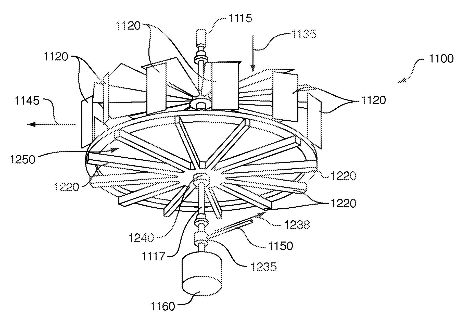
[0040]In accordance with an illustrative embodiment, there is provided an isothermal turbocompressor (with or without an associated turbocondenser and turboexpander) for use in a refrigerant-based air-conditioning system. The system may be implemented for a variety of uses, including a refrigerator, air conditioner, heat pump, and other heating or cooling systems using a compressible refrigerant. The turbocompressor may also be used for the purpose of a more-energy-efficient method for compressing a gas prior to transportation by pipeline or by container. In such cases, the transported gas is broadly termed herein as “refrigerant”, and may be cooled without necessarily changing phase to a liquid. The device is termed a turbocompressor, because it compresses the refrigerant (gas, etc.) via the rotation of a wheel-like spoked turbo fan that will be described in detail below. Likewise, the optional additional components termed a “turbocondenser” and “turboexpander” are called such beca...


PUM


Abstract

This invention provides an isothermal turbocompressor and a combined turbo-compressor-condenser-expander arrangement, which includes heat-transferring blades that are mounted on, or surround, individual conduits to promote air exchange and heat transfer. In operation, the open framework rotates in free air to promote heat exchange. This optimizes contact with free air during rotation. The assembly includes a first plurality of spokes extending radially outwardly from a first central hub to an outer perimeter with first radial conduits that transport refrigerant under centrifugal force and compression from the hub to the outer perimeter. The first radial conduits include heat exchanging blades. A second plurality of spokes extend radially outwardly from a second central hub at an axial spacing from the first central hub. This second plurality of spokes each includes a second thermally-insulated conduit that transports refrigerant from the outer perimeter to the second central hub. Axial conduits extend axially at the outer perimeter, and each interconnects each first radial conduit and each second radial conduit. At least some of the plurality of axial conduits include an axial blade in thermal communication with the conduit that promotes heat exchange radially. A motor rotates a central axis of the turbo-compressor-condenser-expander.

Description

RELATED APPLICATIONS[0001]This application claims the benefit of U.S. Provisional Patent Application Ser. No. 61 / 146,022, filed Jan. 21, 2009, entitled ISOTHERMAL TURBOCOMPRESSOR, the entire disclosure of which is herein expressly incorporated by reference.FIELD OF THE INVENTION[0002]The present invention relates generally to the field of devices used for the compression and condensation of refrigerant in an air-conditioning, refrigeration, heat-pumping, or other cooling / heat-transfer system.BACKGROUND OF THE INVENTION[0003]In air-conditioning, refrigeration, heat-pumping, and other refrigerant-based systems, heat is removed from a colder side of a device or system and transferred to a warmer side. For example in the case of air-conditioning, heat is transferred from the interior of a building, vehicle or other enclosed space to the exterior atmosphere. A standard process of removing colder air from one chamber and transferring it to another chamber or area includes four steps: comp...

Claims


Application Information

Patent Timeline
IPC IPC(8): F25B1/00F04D17/10
CPCB60H1/3223B60H1/3227F04D29/288F04D29/444F04D29/582F25B31/00F25B3/00F28D1/024F28F13/125F04D17/12F25B1/053
Inventor ROISIN, BENOITGEFFKEN, ANDREW S.GRAVES, IAN E.
Owner APPOLLO WIND TECH
Why Eureka
Try Eureka