Shaft arrangement for a transmission

a transmission and shaft arrangement technology, applied in the direction of shafts, bearings, engine lubrication, etc., can solve the problems of high increase of drag moment, low constructive and high effort for supplying bearings and shift clutches with oil. , to achieve the effect of reducing drag loss

Active Publication Date: 2010-09-23
GETRAG GETRIEBE & ZAHNRADFABRIK HERMANN HAGENMEYER GMBH & CO KG
View PDF11 Cites 0 Cited by
  • Summary
  • Abstract
  • Description
  • Claims
  • Application Information

AI Technical Summary

Benefits of technology

[0007]Against this background, it is the object of the invention to provide an improved shaft arrangement that en

Problems solved by technology

Conclusively, the constructive effort for supplying the bearings and the shift clutch arrangement is relatively high.
Here, the constructive effort for supplying the bearing and the shift clutch with oil is relatively low.
However, it is disadvantageous that

Method used


Image

  • Shaft arrangement for a transmission
  • Shaft arrangement for a transmission
  • Shaft arrangement for a transmission

Examples


Embodiment Construction

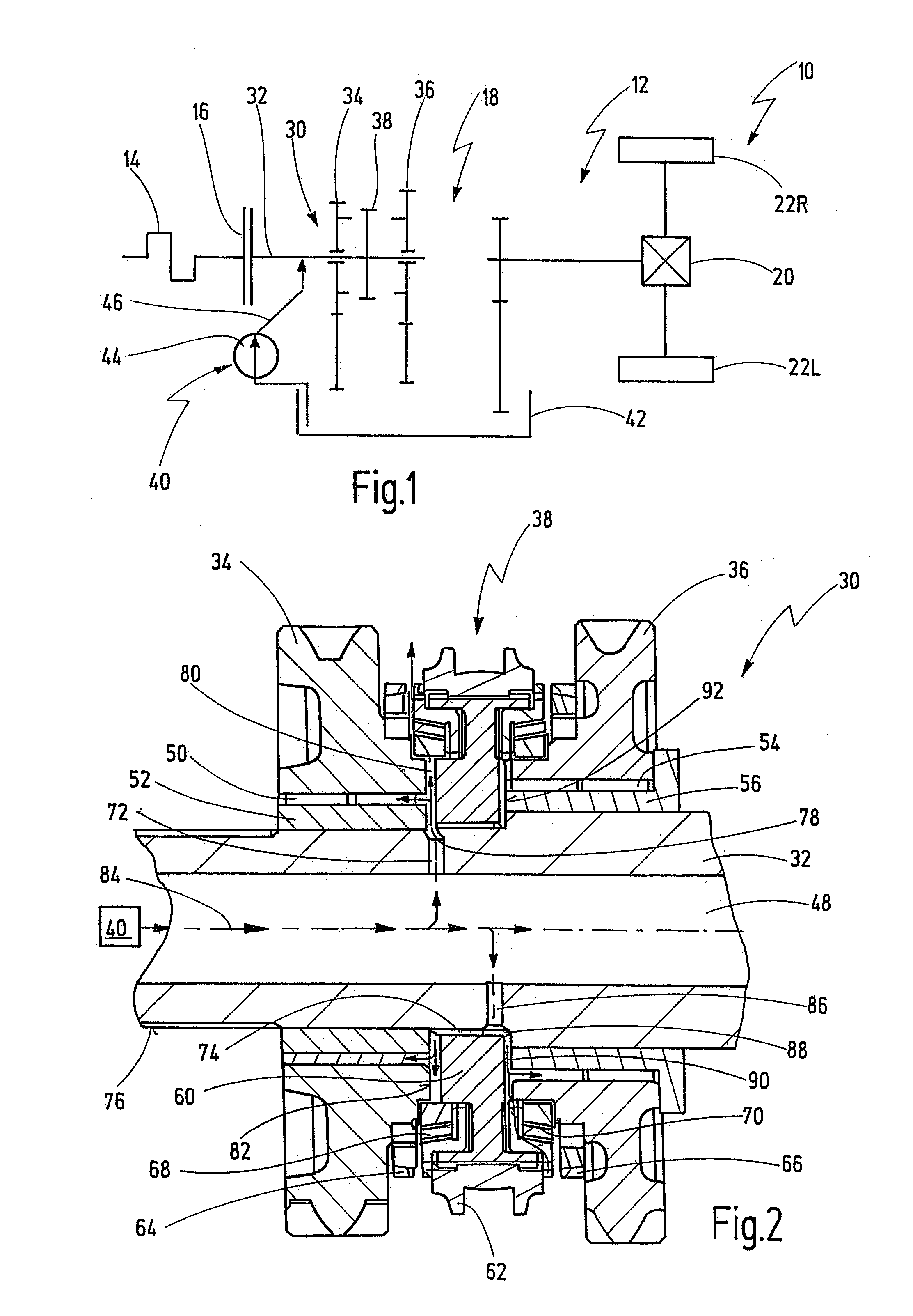
[0050]In FIG. 1, a motor vehicle is depicted schematically and generally shown at 10. The motor vehicle 10 comprises a drive train 12. The drive train 12 comprises a drive motor 14 like a combustion engine, and a separating clutch arrangement 16. Further, the drive train 12 comprises a step transmission 18 having a countershaft layout as well as a differential 20 which distributes the driving force to two driven wheels 22L, 22R.

[0051]The drive train 12 is depicted in a largely schematical manner, in order to make clear that the transmission 18 can, for example, be a manual shift transmission, an automated shift transmission or a double clutch transmission. Further, the clutch arrangement 16 can include a single separating clutch or a double clutch arrangement for a double clutch transmission.

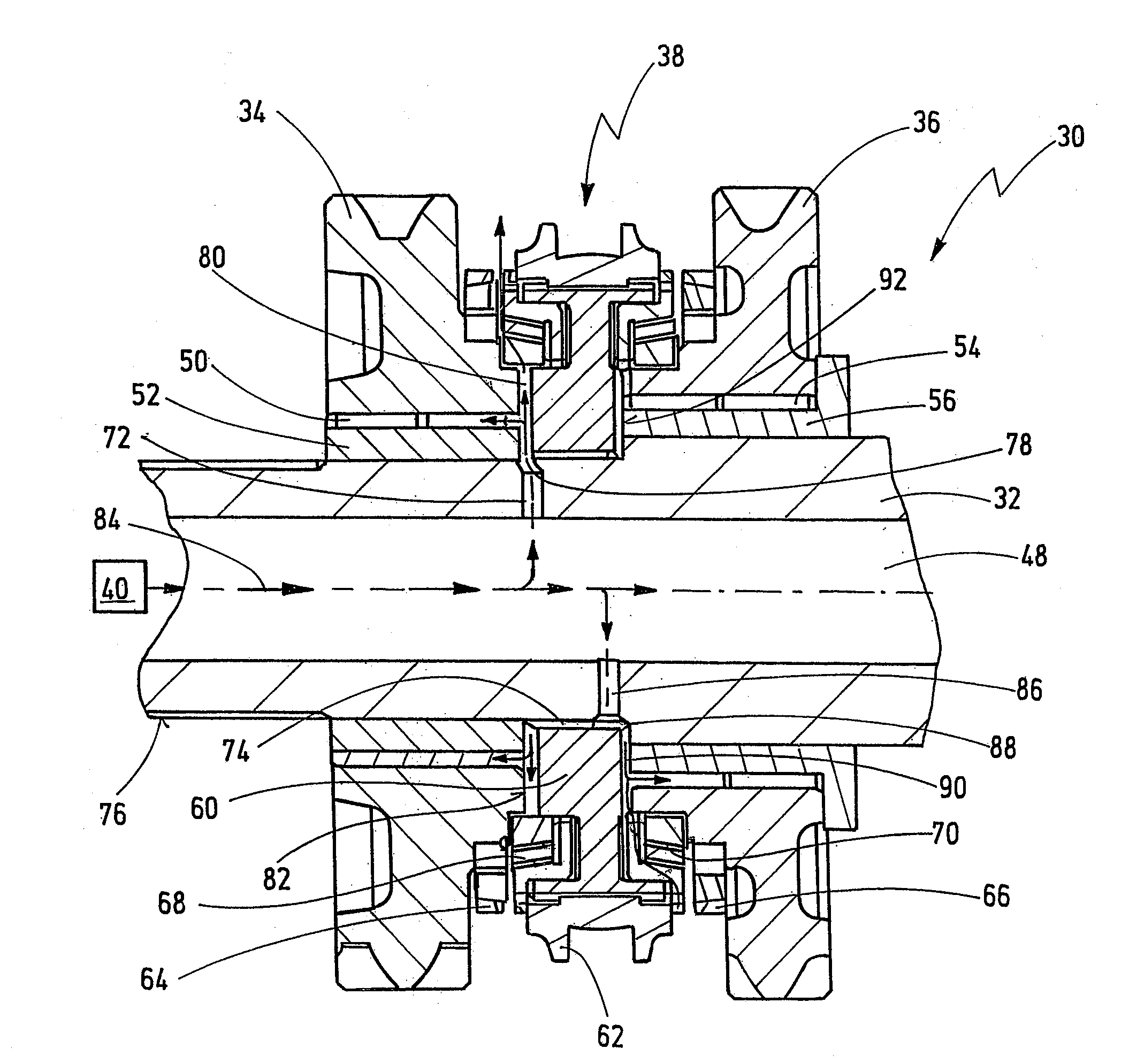
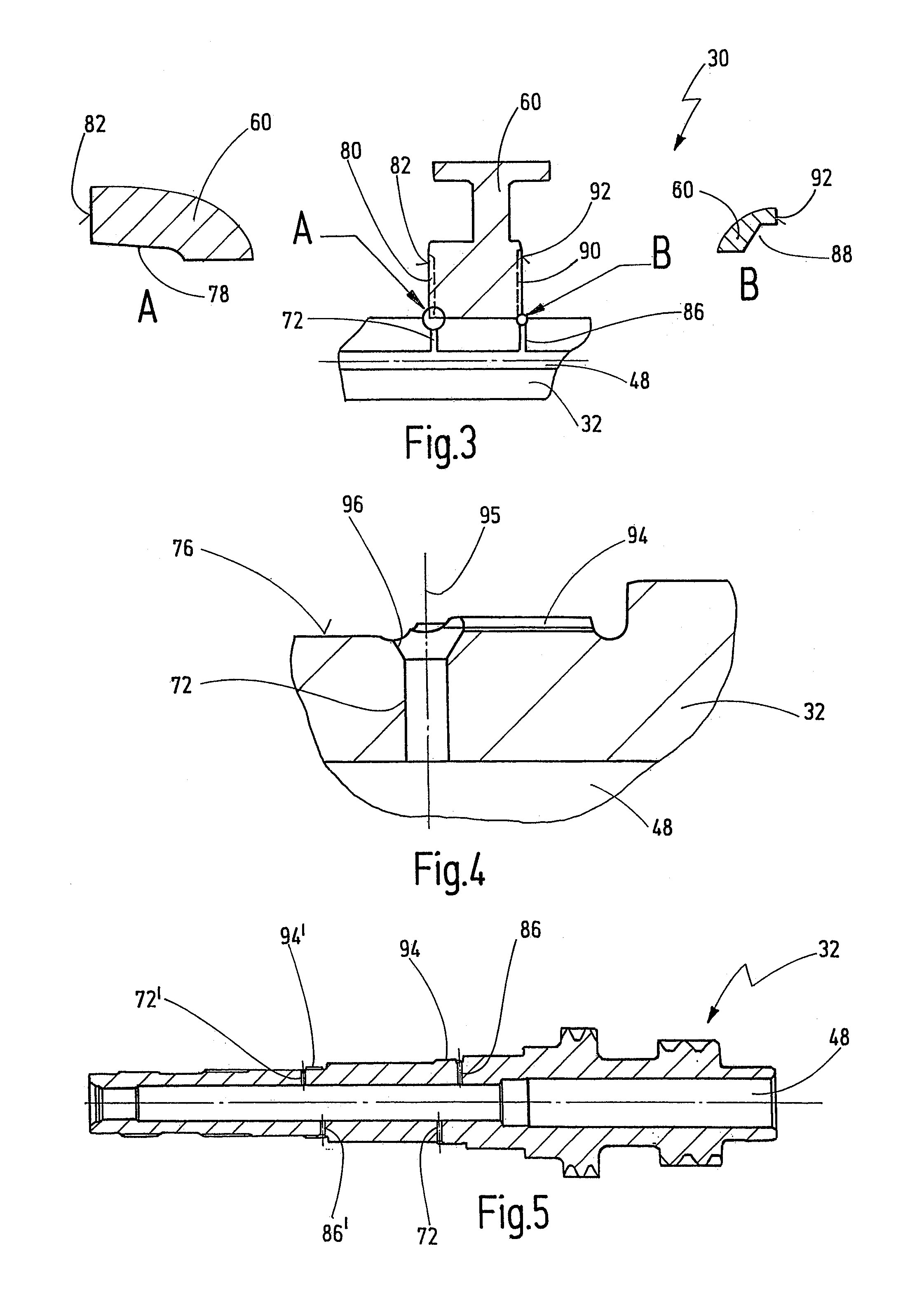
[0052]The step transmission 18 comprises a shaft arrangement 30 according to an embodiment of the invention. The shaft arrangement 30 comprises a shaft 32 which in the present case is formed as ...


PUM


Abstract

A shaft arrangement for a transmission comprises a shaft having an axial bore into which oil can be introduced via an oil supply system, at least one loose wheel which is rotatably supported on the shaft via a bearing, and a shift clutch arrangement which is arranged for connecting the loose wheel with the shaft in a rotationally fixed manner. The shift clutch arrangement comprises a guide sleeve which is connected with the shaft via a tooth engagement in a rotationally fixed manner. The axial bore is connected via at least one transversal bore with the outer circumference of the shaft, so as to supply oil to the bearing and to the shift clutch arrangement. The transversal bore is arranged in an area of the tooth engagement between the guide sleeve and the shaft. A channel is provided in at least one of an area of a toothing of the guide sleeve and an area of the toothing of the shaft, which, together with the guide sleeve toothing, forms the tooth engagement. The channel connects the transversal bore with an area between the guide sleeve and the bearing.

Description

CROSS-REFERENCE TO RELATED APPLICATIONS[0001]This application claims the priority of German utility model application DE 20 2009 003 671.5, filed Mar. 17, 2009.BACKGROUND OF THE INVENTION[0002]The present invention relates to a shaft arrangement for a transmission, particularly for motor vehicles, comprising a shaft having an axial bore into which oil can be introduced via an oil supply system, at least one loose wheel which is rotatably supported on the shaft via a bearing, and a shift clutch arrangement which is arranged for connecting the loose wheel with the shaft in a rotationally fixed manner, said shift clutch arrangement comprising a guide sleeve which is connected with the shaft via tooth engagement in a rotationally fixed manner, wherein the axial bore is connected via at least one transversal bore with the outer circumference of the shaft, so as to supply oil to the bearing and to the shift clutch arrangement, wherein the transversal bore is arranged in an area of the too...

Claims


Application Information

Patent Timeline
IPC IPC(8): F16C3/02
CPCF16D23/06F16H57/0478F16D2300/021
Inventor RUEHLE, GUENTERKESEL, BENJAMIN
Owner GETRAG GETRIEBE & ZAHNRADFABRIK HERMANN HAGENMEYER GMBH & CO KG
Why Eureka
Try Eureka