Sterilizable vacuum handpiece

a vacuum handpiece and sterile technology, applied in the field of sterile vacuum handpieces, can solve the problems of obscuring the field of surgery, affecting the effect of suction,

Inactive Publication Date: 2010-09-30
CLIFF JOHN A
View PDF42 Cites 4 Cited by
  • Summary
  • Abstract
  • Description
  • Claims
  • Application Information

AI Technical Summary

Benefits of technology

[0009]In its most general configuration, the claimed sterilizable vacuum handpiece advances the state of the art with a variety of new capabilities and overcomes many of the shortcomings of prior devices in new and novel ways. In its most general sense, the handpiece overcomes the shortcomings and limitations of the prior art in any of a number of generally effective configurations. The handpiece demonstrates such capabilities and overcomes many of the shortcomings of prior methods in new and novel ways.

Problems solved by technology

The surgical operator needs a means to evacuate these materials, lest they obscure the field of surgery and complicate the procedure.
As such, these devices have numerous limitations.
If allowed to be in continuous connection to suction, such devices are noisy and distracting, and their continuous suction causes them to adhere themselves to human or animal tissue, possibly causing damage to delicate structures.
Such devices are also noisy when running with a side-channel open, and require a continuous application of the thumb or finger to occlude the side port in order to produce usable suction in the surgical field, thus potentially robbing the operator of the substantial use of one hand.
These simple devices also pose considerable challenges in the regulation of high and low suction levels.
With the side-channel suction device, suction can be somewhat varied by partially to completely occluding the side-channel, but this is inaccurate and manually difficult.
A simple slip of the thumb or the finger of a fraction of a millimeter can result in full suction being applied, often at a very inopportune moment.
Valves may be incorporated into the suction device to address the above problems, but these bring their own attendant issues.
Additionally, the inherent complexity of many valves make such devices difficult to clean and sterilize after use, or conversely, expensive if they are to be disposed of after use.

Method used


Image

  • Sterilizable vacuum handpiece
  • Sterilizable vacuum handpiece
  • Sterilizable vacuum handpiece

Examples


Embodiment Construction

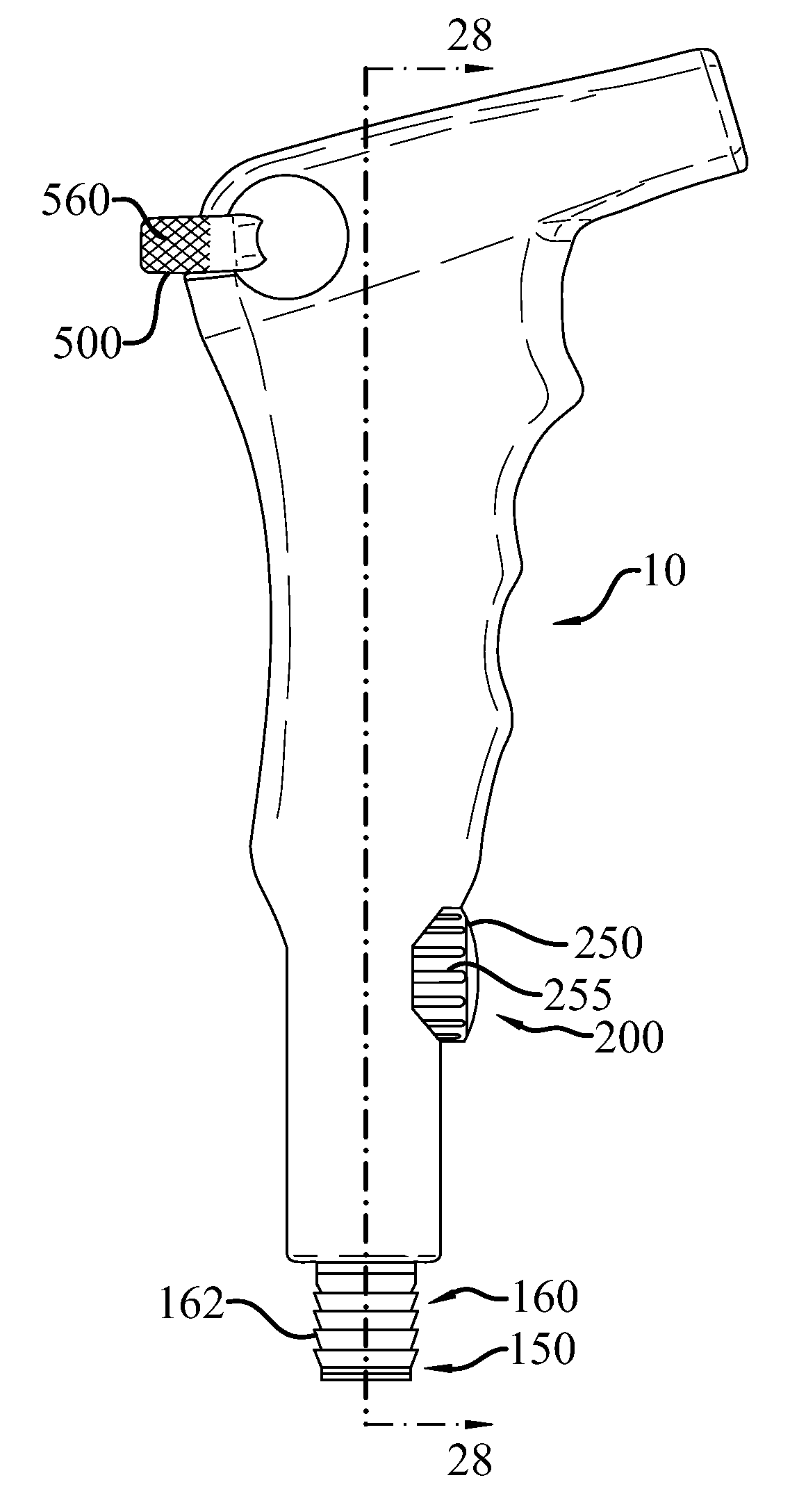
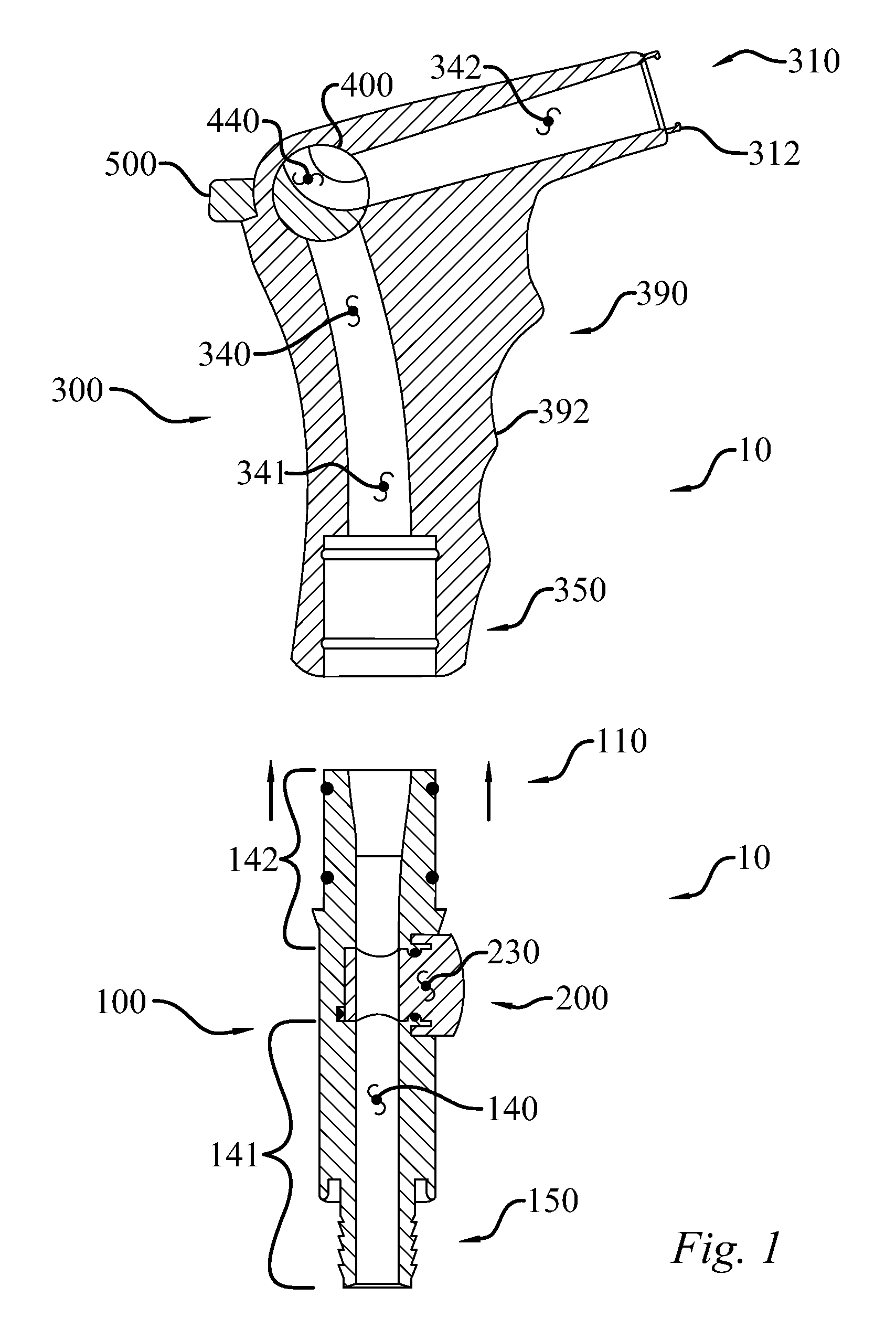
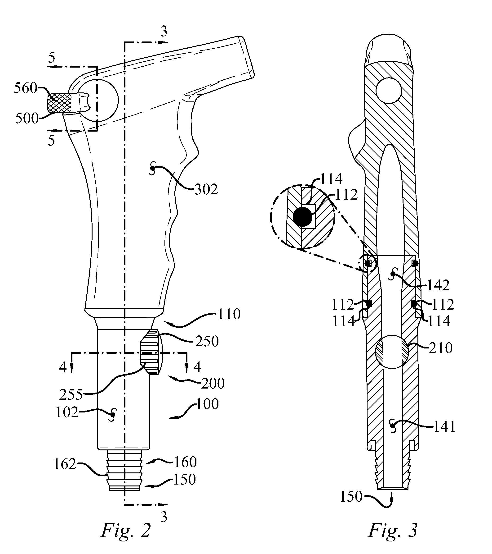
[0055]The claimed sterilizable vacuum handpiece (10) enables a significant advance in the state of the art. The preferred embodiments of the handpiece (10) accomplish this by new and novel arrangements of elements and methods that are configured in unique and novel ways and which demonstrate previously unavailable but preferred and desirable capabilities. The detailed description set forth below in connection with the drawings is intended merely as a description of the present embodiments of the claimed handpiece (10), and is not intended to represent the only form in which the handpiece (10) may be constructed or utilized. The description sets forth the designs, functions, means, and methods of implementing the handpiece (10) in connection with the illustrated embodiments. It is to be understood, however, that the same or equivalent functions and features may be accomplished by different embodiments that are also intended to be encompassed within the spirit and scope of the claimed...


PUM


Abstract

A sterilizable vacuum handpiece that may include a base unit reversibly coupled to a handle unit, having a central vacuum passage connecting proximal and distal ends. A hand-removable base unit valve may divide a base unit vacuum passage and a hand-removable handle unit valve may separate a handle unit vacuum passage, in adjustable fluid communication with each other. The valves may be retained within bores and counter-bores, and may achieve fluid-tight fit with O-rings retained within the valves. The valves may have vacuum passages with surface areas greater than or equal to a least diameter of the vacuum passage containing the valve. In at least one embodiment, the handle valve is releasably retained by the opposing ends of a “bucket-handle” shaped controller. Alternatively, the handpiece may be formed as a single combined unit, where the terms base unit and handle unit refer only to regions of an otherwise unified structure.

Description

STATEMENT REGARDING FEDERALLY SPONSORED RESEARCH OR DEVELOPMENT[0001]This invention was not made as part of a federally sponsored research or development project.TECHNICAL FIELD[0002]The instant invention relates to a sterilizable vacuum handpiece, particularly to a device for applying suction in medical, dental, and veterinary applications that may be disassembled for cleaning and sterilization.BACKGROUND OF THE INVENTION[0003]Surgical suction devices are commonly used in wide variety of surgical procedures in the medical, dental, and veterinary fields. During a surgical procedure, varying amounts of blood, mucus and small surgical debris are produced. The surgical operator needs a means to evacuate these materials, lest they obscure the field of surgery and complicate the procedure. In the dental field, such suction devices are often colloquially known as “handpieces.”[0004]At its simplest, some of the simplest prior art devices are nothing more than a flexible or rigid tube attac...

Claims


Application Information

Patent Timeline
Patent Type & Authority Applications(United States)
IPC IPC(8): A61M39/22
CPCA61C17/043A61M39/22A61M1/0043A61C17/08A61M1/7413
Inventor CLIFF, JOHN A.
Owner CLIFF JOHN A
Why Eureka
Try Eureka