Actuating device having a locking roller

a technology of locking roller and actuating device, which is applied in the direction of mechanical control device, process and machine control, instruments, etc., can solve the problems of limiting the design of the desired range of motion or the number of shift stages of the shift lever, and achieve the effect of reliably adjusting the rotation angle position

Inactive Publication Date: 2010-10-21
ZF FRIEDRICHSHAFEN AG
View PDF14 Cites 8 Cited by
  • Summary
  • Abstract
  • Description
  • Claims
  • Application Information

AI Technical Summary

Benefits of technology

[0033]These embodiments make possible a cost-saving design of the actuating device having only one single electric motor actuator that can nevertheless activate all different actuating locks of the shift lever—in the various shift tracks of an H shift pattern, for example—in a targeted manner.
[0034]According to a further preferred embodiment of the invention, a rotation angle sensor is provided disposed on at least one locking roller. This makes it possible to drive and reliably adjust the rotation angle position, which is required for the particular lock, of the locking roller or locking rollers even using a relatively simple electric motor that can therefore function without the use of a separate sensor system.
[0035]According to a further preferred embodiment of the invention, it is furthermore provided that a return spring is disposed on at least one locking roller. The return spring, which can be designed e.g. in the form of a flat spiral spring, makes it possible to actuate the shift lever in particular even if the actuator drive of the locking rollers should fail, or after the ignition is shut off. In this case, the locking rollers are rotated back, using the energy stored in the return spring, to a predetermined position in which all actuating positions of the shift lever can be selected.

Problems solved by technology

Nevertheless, a great deal of freedom still exists in regards to designing the desired ranges of motion or the number of shift stages for the shift lever, which is limited only by the largely unrestricted shaping of the locking chamber assembly in the locking roller.

Method used


Image

  • Actuating device having a locking roller
  • Actuating device having a locking roller
  • Actuating device having a locking roller

Examples


Embodiment Construction

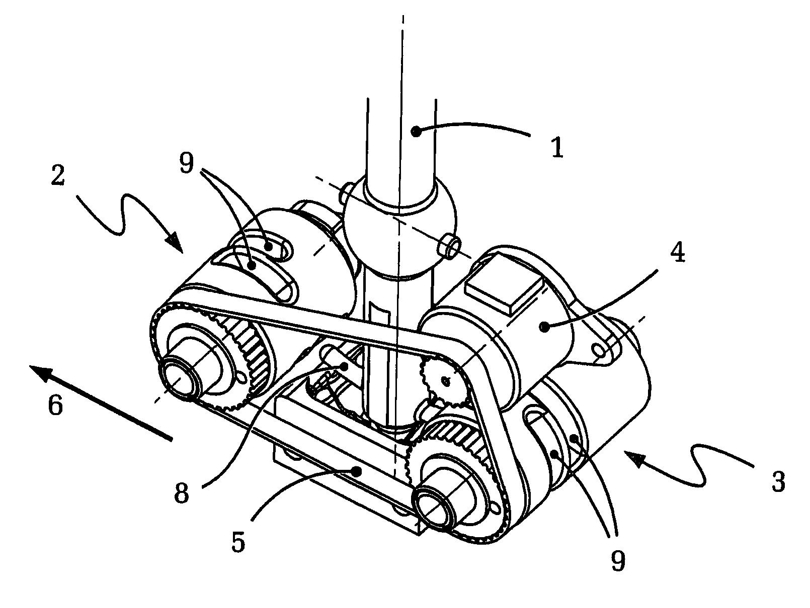
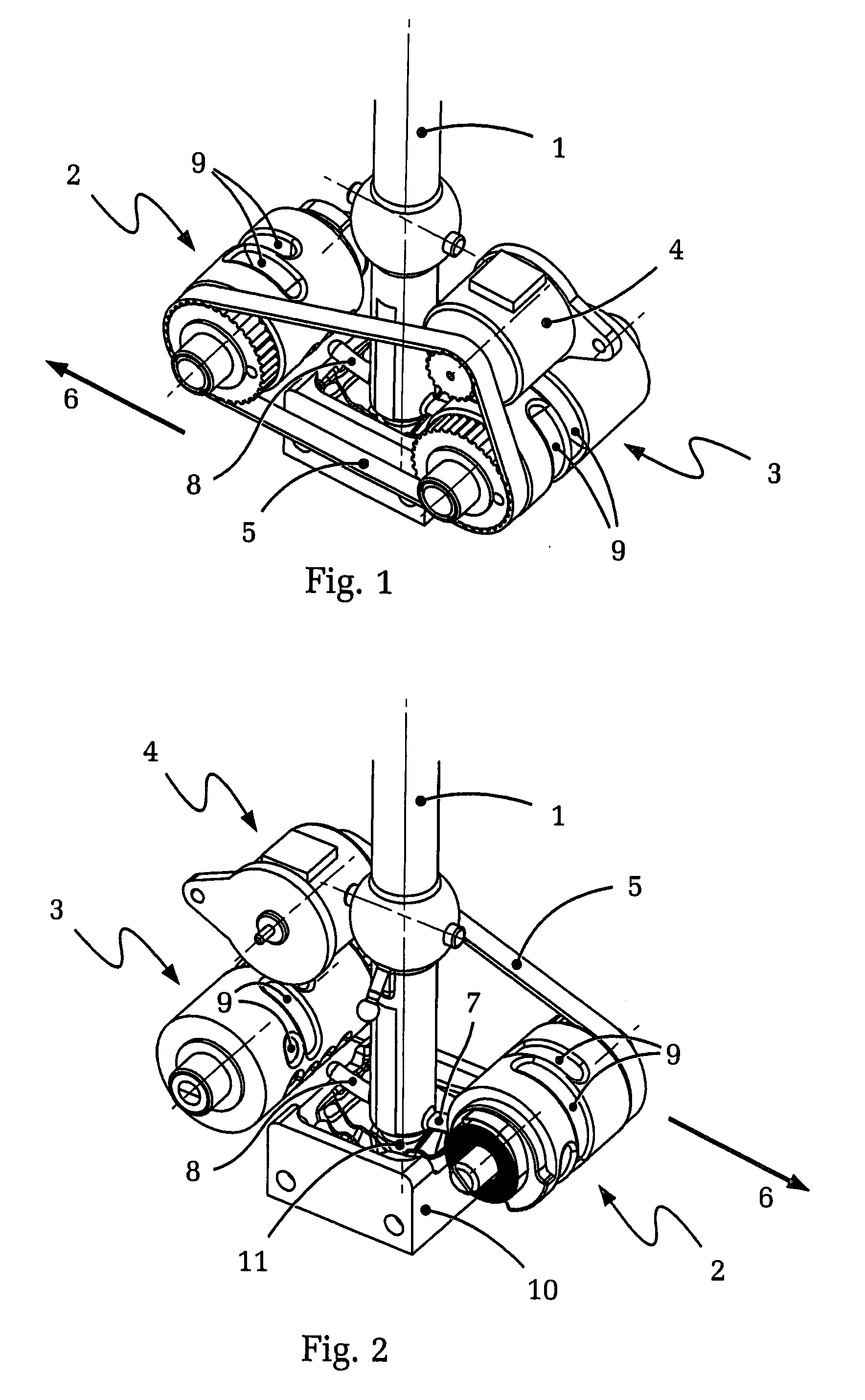
[0044]FIG. 1 shows, in a schematic, isometric view, the lockout mechanism for an embodiment of an actuating device according to the present invention, in a view looking upon the toothed-belt drive. The illustration clearly shows (only partially, for reasons of space) shift lever 1, locking rollers 2 and 3, and electric motor drive 4 and its toothed-belt drive 5 for controlling the rotation of locking rollers 2 and 3. Direction arrow 6 indicates the direction of travel of the motor vehicle that applies for this embodiment.

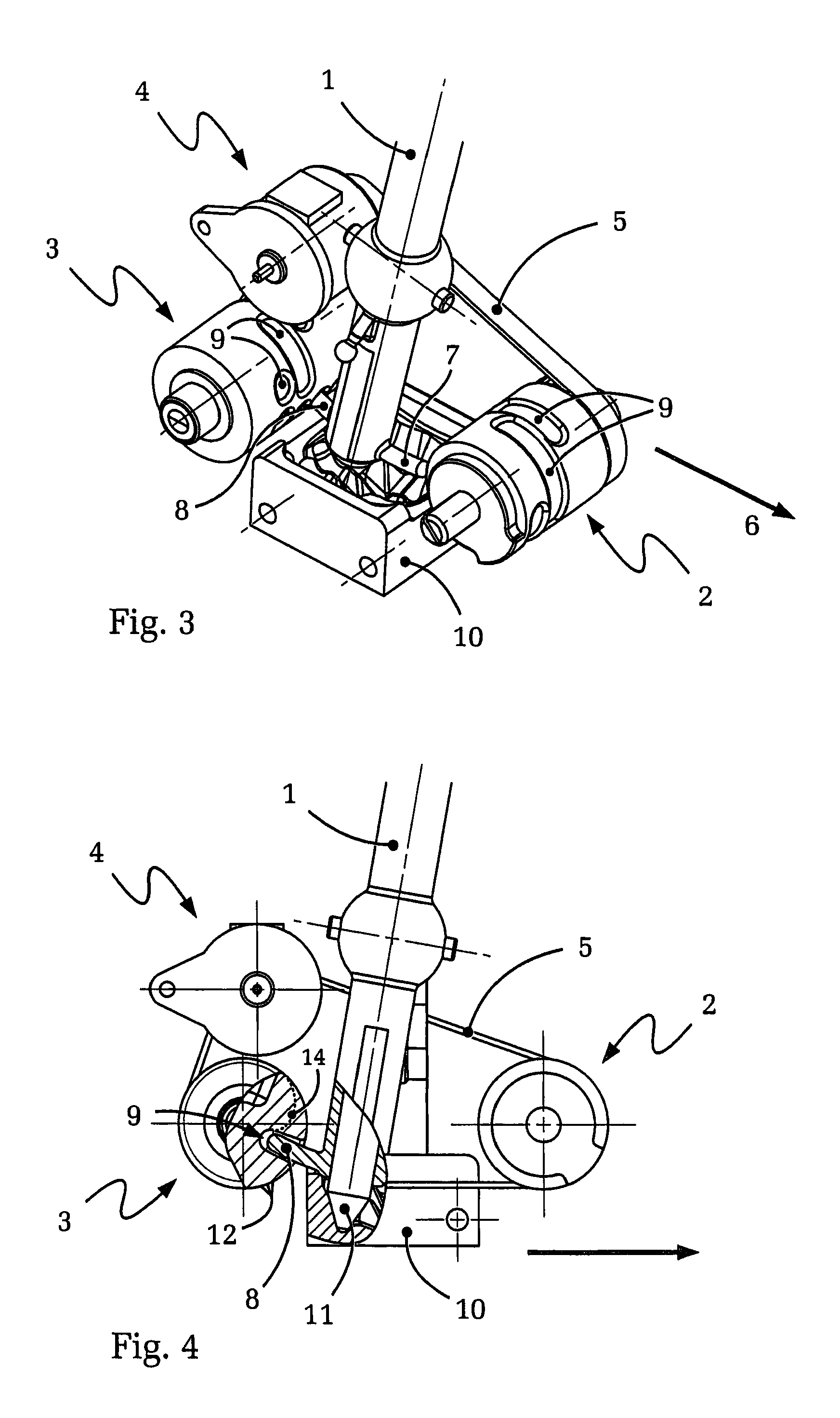
[0045]FIG. 2 shows the situation according to FIG. 1 from the opposite viewing direction, looking upon locking rollers 2, 3 and electric motor 4. FIG. 2 shows, in particular, locking cams 7, 8 which are disposed on shift lever 1 and, in this embodiment, are formed as a single piece with shift lever 1. Locking cams 7, 8 are disposed such that they are inserted into corresponding locking chambers 9 of locking rollers 2, 3 when shift lever 1 is swivelled.

[0046]Dependin...


PUM


Abstract

An actuating device for selecting fixed gear ratios of a gear shifting transmission. The actuating device comprises a shift lever movable between at least three gear positions, and a lockout mechanism for limiting the range of motion of the shift lever. The lockout mechanism comprises a locking assembly including at least one locking chamber disposed in at least one locking roller, and the shift lever includes at least one locking cam. The locking cam can be inserted into the locking chamber to limit the range of motion of the shift lever. It is thus possible to implement actuating and locking tasks in the field of shift-by-wire transmissions, in a simple way and with minimal construction space requirements. The actuating device produces minimal noise and has short shifting times, and makes it shift-by-wire-controlled H shift patterns possible.

Description

[0001]This application is a National Stage completion of PCT / DE2008 / 050038 filed Dec. 4, 2008, which claims priority from German patent application serial no. 10 2007 062 824.4 filed Dec. 21, 2007.FIELD OF THE INVENTION[0002]The invention relates to an actuating device for a gear shifting transmission, e.g. for an automated manual transmission having shift-by-wire actuation.BACKGROUND OF THE INVENTION[0003]Gear shifting transmissions of motor vehicles are shifted or controlled in general using an actuating device located within reach of the driver. Actuating elements such as shift levers or selector levers are used regularly for this purpose, and are located, for example between the front seats of the motor vehicle or in other regions of the cockpit.[0004]In the case of manually shifted transmissions in particular, purely mechanical actuating devices and transfer means are often still used between the actuating element and the gear shifting transmission. These can be mechanical tran...

Claims


Application Information

Patent Timeline
Patent Type & Authority Applications(United States)
IPC IPC(8): G05G1/04
CPCF16H59/02F16H59/044F16H61/22Y10T74/2011Y10T74/19251Y10T74/20085Y10T74/20582
Inventor GIEFER, ANDREASRAKE, LUDGERROSENTRETER, SASCHA
Owner ZF FRIEDRICHSHAFEN AG
Why Eureka
Try Eureka