Check valve and piston pump having check valve

Inactive Publication Date: 2010-12-30
PRETTL ROLF
View PDF10 Cites 7 Cited by
  • Summary
  • Abstract
  • Description
  • Claims
  • Application Information

AI Technical Summary

Benefits of technology

[0025]As a result, with a relatively small amount of constructional space, a high throughflow volume may be achieved. The valve, as a result, contains two parallel check valves. In this manner, the radial forces which occur may also be compensated relative to one another. Thus this configuration is preferably also suitable for when the check valve is part of a system which is movable in the flow direction, for example arranged on a piston.
[0088]The piston rod may, as a result, be guided in the manner of air suspension so that the frictional effect which occurs is minimized.

Problems solved by technology

A drawback with such check valves is, on the one hand, the large number of components.
This leads to a relatively low degree of efficiency.
This may be undesirable in closed circuits.
Moreover, it may also be undesirable if the fluid has the tendency to crystallize or to form clumps when at a standstill.

Method used


Image

  • Check valve and piston pump having check valve
  • Check valve and piston pump having check valve
  • Check valve and piston pump having check valve

Examples


Embodiment Construction

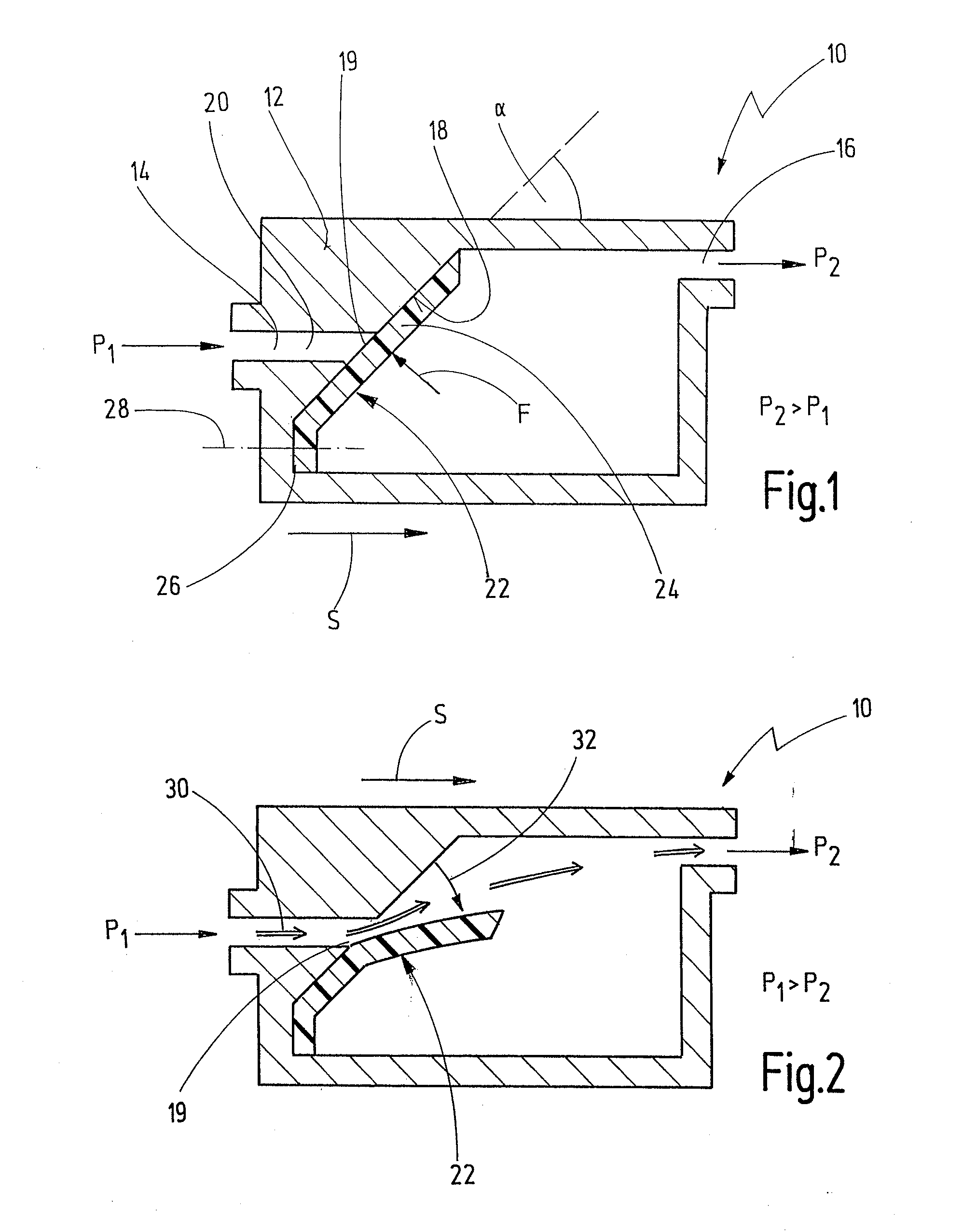
[0115]In FIG. 1 a first embodiment of a check valve according to the invention is denoted by 10. The check valve 10 has a valve housing 12. The valve housing separates a first pressure chamber 14 in which a fluid has a first fluid pressure P1, from a second pressure chamber 16, in which the fluid has a second pressure P2.

[0116]In the inside of the valve housing 12 a valve chamber is formed which is connected to the second pressure chamber 16.

[0117]The check valve sets a flow direction S via which fluid may pass from the first pressure chamber 14 into the second pressure chamber 16. The flow direction S is parallel to a longitudinal extension of the check valve 10.

[0118]One side of the valve chamber facing the first pressure chamber 14 is configured as a valve seat 18. The valve seat 18 is thus formed as an oblique surface, which relative to the flow direction S encompasses an angle which is greater than 15° and less than 80°, in particular greater than 30° and less than 60°, in the ...


PUM


Abstract

A check valve for arranging between a first pressure chamber, in which a first pressure prevails, and a second pressure chamber in which a second pressure prevails. The valve comprises a valve housing on which a valve seat is formed, and comprises a blocking element which is designed in a blocking position, to close a valve opening in the region of the valve seat, in order to block a connection between the first and the second valve chambers, and is designed in an open position to release the valve opening in order to release the connection between the first and the second valve chambers. The valve seat is configured as an oblique surface, which relative to the flow direction is aligned at an angle which is greater than 15° and less than 80°. The blocking element comprises a planar blocking lobe made from an elastically deformable material which in the blocking position bears against the oblique surface, and in the open position lifts away from the oblique surface in order to release the connection.

Description

CROSS-REFERENCE TO RELATED APPLICATIONS[0001]This is a Continuation application of International patent application PCT / EP 2009 / 000163, filed Jan. 14, 2009, which claims the priority of German patent application DE 10 2008 006 686, filed Jan. 21, 2008.BACKGROUND OF THE INVENTION[0002]The present invention relates to a check valve for arranging between a first pressure chamber, in which a first pressure of a fluid prevails, and a second pressure chamber, in which a second pressure prevails, comprising a valve housing on which a valve seat is formed, and comprising a blocking element which is designed in a blocking position to close a valve opening in the region of the valve seat, in order to block a connection between the first and the second valve chambers when the second pressure is greater than the first pressure and is designed in an open position to release the valve opening in order to release the connection between the first and the second valve chambers when the first pressur...

Claims


Application Information

Patent Timeline
IPC IPC(8): F04B53/10F16K15/02
CPCF04B1/0452F04B53/1052F16K15/031F01N2610/1433F16K15/14F01N2610/02F01N2610/14F16K15/038Y10T137/7837
Inventor BORST, PETERENGEL, MARKUS
Owner PRETTL ROLF
Why Eureka
Try Eureka