Arrangement of a Rotor Position Sensor

a technology of rotor position sensor and arrangement, which is applied in the direction of fluid gearing, transportation and packaging, gearing, etc., can solve the problems of structural complexity and cost of arrangement of rotor position sensor and associated or corresponding sensor track in hybrid transmission, and achieve cost-effective

Active Publication Date: 2020-04-23
ZF FRIEDRICHSHAFEN AG
View PDF1 Cites 0 Cited by
  • Summary
  • Abstract
  • Description
  • Claims
  • Application Information

AI Technical Summary

Benefits of technology

[0006]Example aspects of the present invention provide an arrangement of a rotor position sensor as well as a hybrid transmission housing that includes the arrangement, which allow for a structurally simple and cost-effective arrangement of the rotor position sensor and the sensor track.

Problems solved by technology

Regardless of whether an axially or radially scanning rotor position sensor is utilized, the arrangement of the rotor position sensor and the associated or corresponding sensor track in the hybrid transmission is structurally complex and costly, since, on the one hand, components are necessary on the housing side, to which the rotor position sensor is attached and, on the other hand, components are necessary on the torque-converter side, to which the concurrently-rotating sensor track is attached.
In addition, in the case of hybrid transmissions that include a torque converter, the problem arises that the torque converter expands in the longitudinal direction or on an axial side in the area of the torque converter hub during the operation of the automatic transmission due to the internal pressure, which is referred to as so-called torque converter ballooning.

Method used


Image

  • Arrangement of a Rotor Position Sensor
  • Arrangement of a Rotor Position Sensor
  • Arrangement of a Rotor Position Sensor

Examples


Embodiment Construction

[0022]Reference will now be made to embodiments of the invention, one or more examples of which are shown in the drawings. Each embodiment is provided by way of explanation of the invention, and not as a limitation of the invention. For example, features illustrated or described as part of one embodiment can be combined with another embodiment to yield still another embodiment. It is intended that the present invention include these and other modifications and variations to the embodiments described herein.

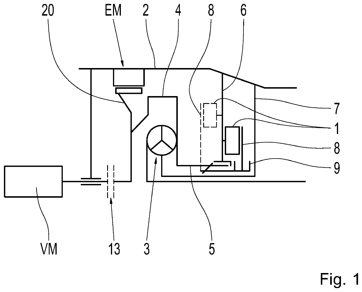
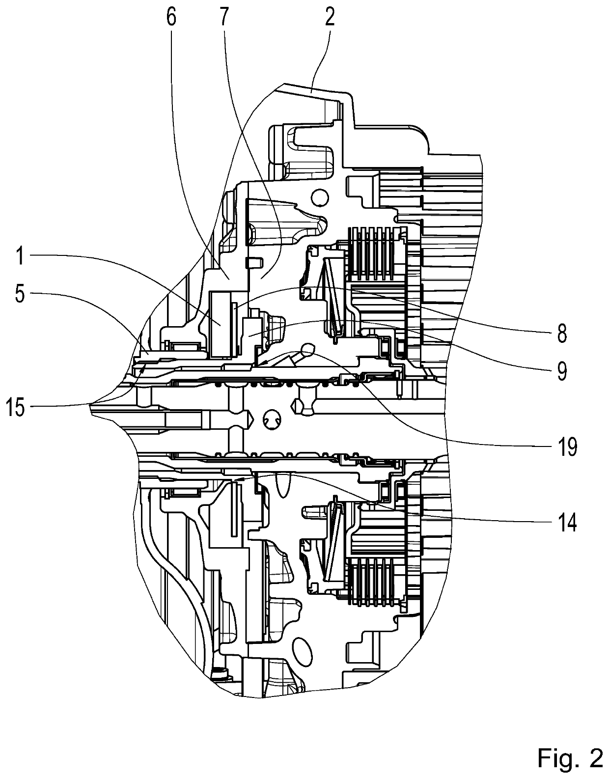
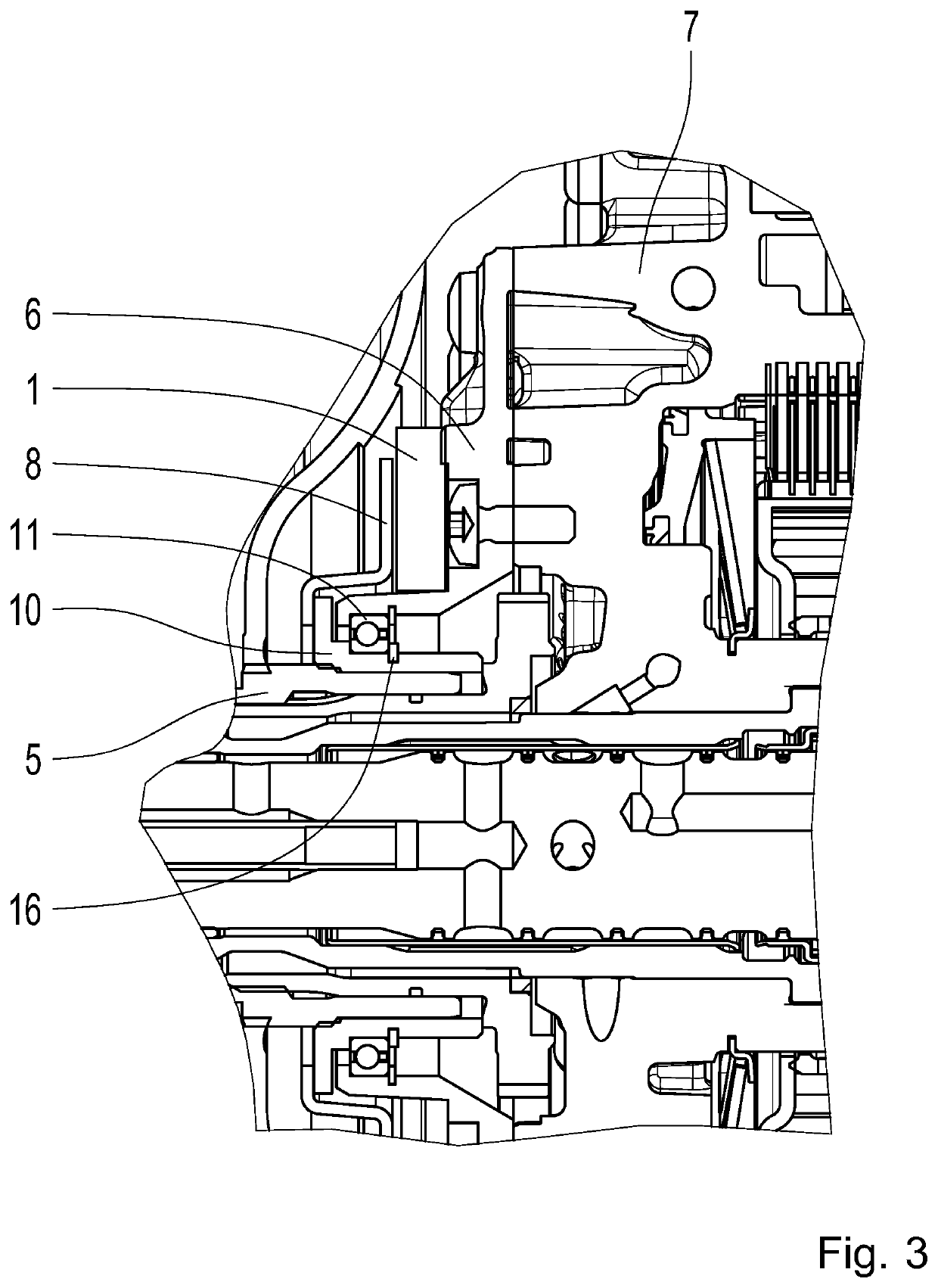
[0023]FIGS. 1 to 6 show various arrangement variants, according to example aspects of the invention, of a sensor track-scanning rotor position sensor 1, 1 A of an electric machine EM in a hybrid transmission housing 2 including a torque converter 3 and a housing-affixed oil supply plate arrangement, by way of example.

[0024]FIG. 1 shows a diagrammatic view of the hybrid transmission housing 2 including various possible arrangements of the rotor position sensor 1, 1 A. The various p...


PUM


Abstract

An arrangement of at least one sensor track-scanning rotor position sensor (1, 1 A) of an electric machine (EM) in a hybrid transmission housing (2) that includes a torque converter (3) and a housing-affixed oil supply plate arrangement is provided. The rotor position sensor (1, 1 A) is attached on an oil-supply-plate side, and a sensor ring (8), as a sensor track, is attached on a converter side. A hybrid transmission housing (2) including the arrangement is also provided.

Description

CROSS-REFERENCE TO RELATED APPLICATION[0001]The present application is related and has right of priority to German Patent Application No. 10 2018 218 118.7 filed on Oct. 23, 2018, the entirety of which is incorporated by reference for all purposes.FIELD OF THE INVENTION[0002]The present invention relates generally to an arrangement of a rotor position sensor of an electric machine in a hybrid transmission housing. Moreover, the invention relates generally to a hybrid transmission housing that includes the arrangement of a rotor position sensor.BACKGROUND[0003]It is generally known from automotive engineering that a rotor position sensor is utilized in electric prime movers in hybrid transmissions to determine the position and the rotational speed of a rotor of the electric machine. Such input data is necessary for control of the electric machine. Eddy current sensors and variable reluctance (VR) resolver sensors, for example, can be utilized as a rotor position sensor, wherein eddy ...

Claims


Application Information

Patent Timeline
Patent Type & Authority Applications(United States)
IPC IPC(8): F16H57/02G01D5/12
CPCF16H57/02F16H2057/02043F16H2045/0215G01D5/12F16H45/02F16H57/0427F16H2057/02026G01D5/20B60K2006/4825F16H57/0441H02K7/116H02K11/21B60K6/485B60K6/48Y02T10/62F16H2057/0216F16H2057/02034
Inventor ESCHENBECK, LINUSRIEDISSER, THOMASSCHILLING, CARLGEIGER, ANDREASVIERNEKES, GERALDWEIDNER, MATTHIASRÖSSNER, MONIKAALLNOCH, CHRISTOPHER
Owner ZF FRIEDRICHSHAFEN AG
Why Eureka
Try Eureka