Method and device for calibrating a magnetic induction tomography system

a magnetic induction tomography and imaging system technology, applied in the direction of instruments, liquid/fluent solid measurements, diagnostic recording/measuring, etc., can solve the problems of system accuracy, long time required for system work, affecting the accuracy of measurement, etc., to improve image quality and minimize magnetic interference

Inactive Publication Date: 2011-01-06
KONINKLIJKE PHILIPS ELECTRONICS NV
View PDF4 Cites 8 Cited by
  • Summary
  • Abstract
  • Description
  • Claims
  • Application Information

AI Technical Summary

Benefits of technology

[0019]By emptying the conductive fluid from the cavity of the reference object, only the non-conductive envelope of the reference object is left in the m

Problems solved by technology

The system is required to work for a long time in this case.
The system offset, especially the offset caused by temperature, may affect the accuracy of the measurement.
All of these changes may affect the system accuracy that is required to m

Method used


Image

  • Method and device for calibrating a magnetic induction tomography system
  • Method and device for calibrating a magnetic induction tomography system
  • Method and device for calibrating a magnetic induction tomography system

Examples


Embodiment Construction

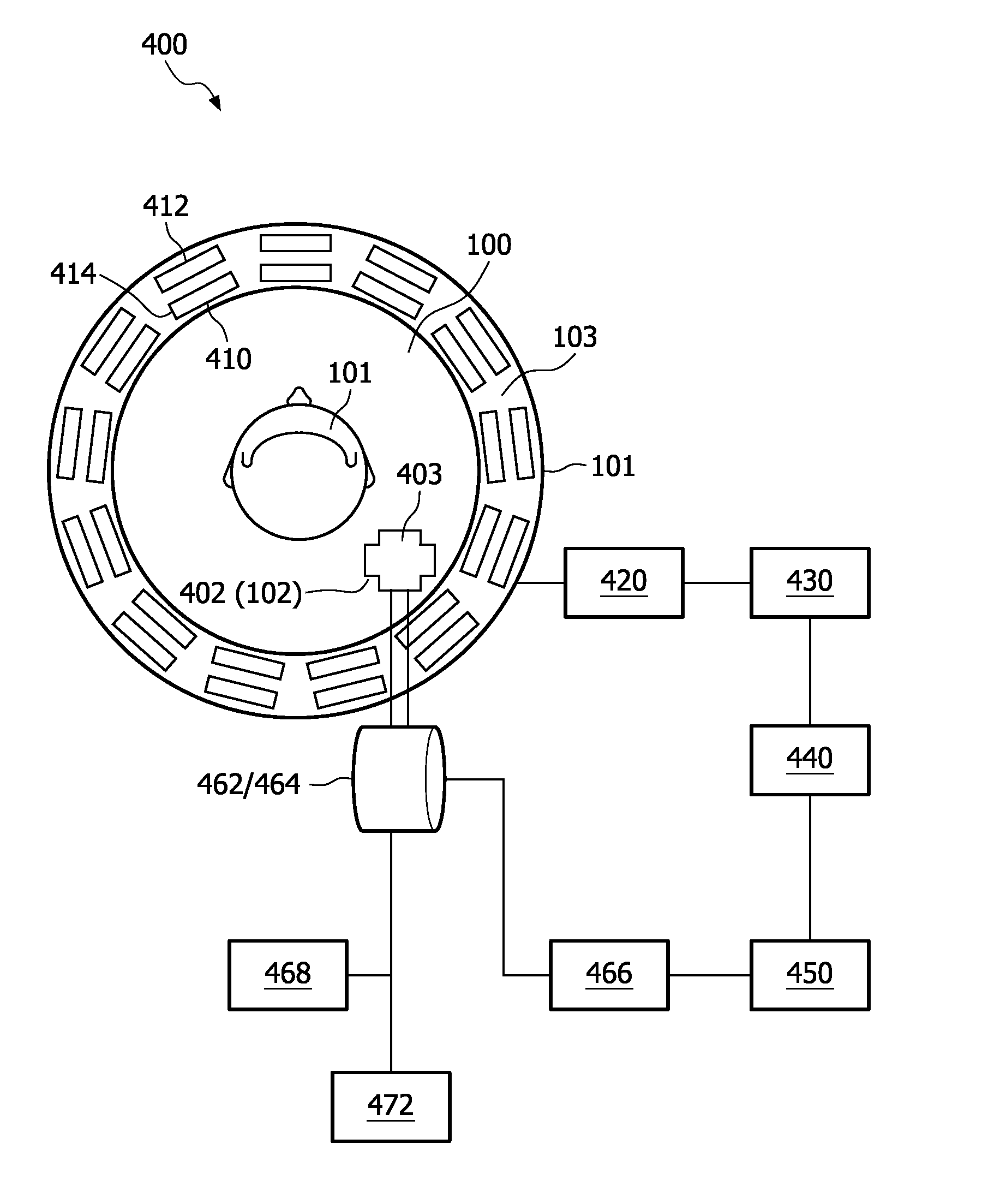
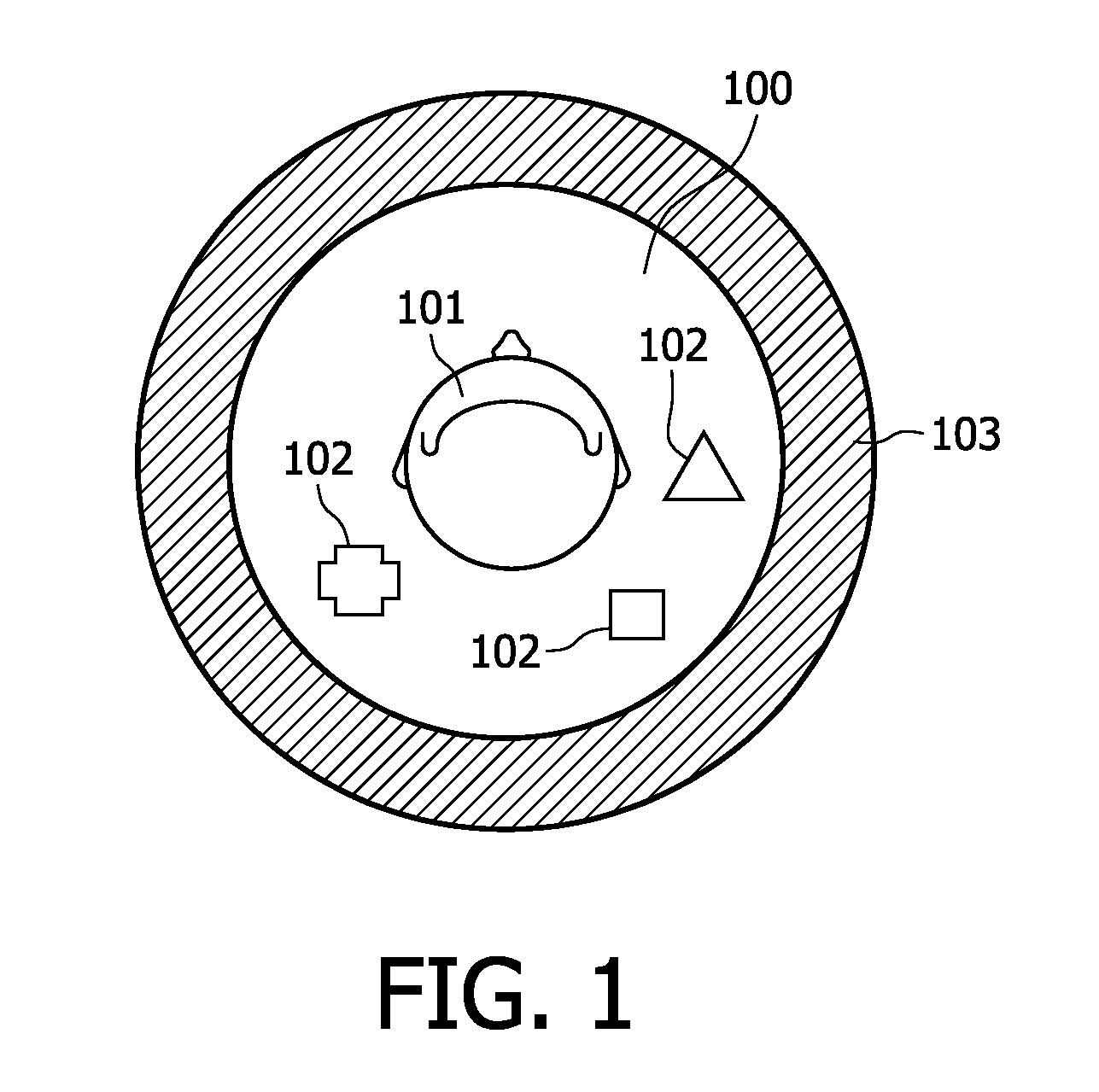
[0034]FIG. 1 is a schematic diagram showing, by way of example, an embodiment of the measurement chamber of an imaging system according to the invention.

[0035]In the embodiment shown in FIG. 1, the measurement chamber 100, which is a part of an imaging system, is formed by a circular body 103 and is intended to accommodate objects to be imaged. The objects to be imaged define an object of interest 101 for imaging, such as the patient's head, or other parts of his body. The objects to be imaged may also include one or more reference objects 102, which may be used for calibrating the offset of the imaging system as explained hereinafter.

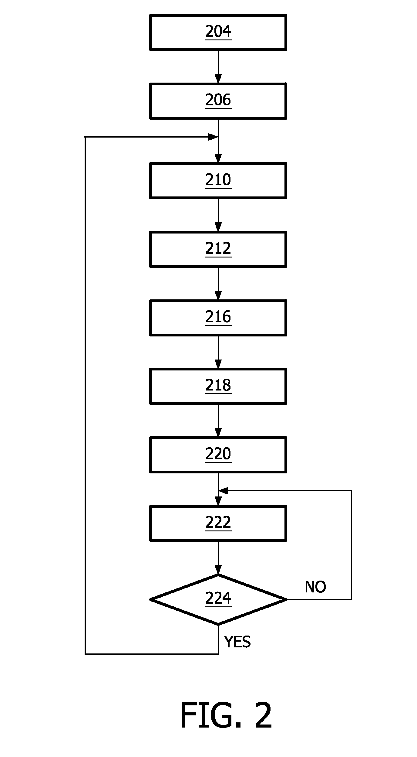
[0036]FIG. 2 is a first flowchart of a method of calibrating the offset of an imaging system.

[0037]According to the invention, the method comprises a first step 204 of measuring magnetic induction signals associated with the reference object 102 placed in the measurement chamber 100 of the system so as to obtain a first set of measurement data. The ref...


PUM


Abstract

This invention relates to a method and device for calibrating the offset of an imaging system. The core idea of the invention is to place a reference object in the measurement chamber of the imaging system, measure the signals associated with the reference object at different points of time, calculate the merit function based on changes of the parameters representing the electromagnetic property of the reference object, and derive an optimal set of offset data that minimizes the value of the merit function for compensating the offset of the system in subsequent image reconstructions. In one embodiment, the invention uses a reference object comprising a non-conductive envelope and a cavity which can be filled with a conductive fluid and emptied, and in this way reduces the imaging interference caused by the reference object during monitoring.

Description

FIELD OF THE INVENTION[0001]The invention relates to a method and device for calibrating an imaging system, for example, a magnetic induction tomography system.BACKGROUND OF THE INVENTION[0002]Magnetic induction tomography (MIT) is a non-invasive imaging technique with applications in industry and medical imaging. In contrast to other electrical imaging techniques, MIT does not require direct contact of the sensors with the object to be imaged.[0003]MIT applies a magnetic field from one or more generator coils (also called excitation coils) to induce eddy currents in the object (i.e. material) to be studied. In other words, the scanning region is excited with a time-varying magnetic field. The presence of conductive and / or permeable material distorts the energizing field within. The perturbation of said primary magnetic field, i.e. the secondary magnetic field resulting from the eddy currents, is detected by a number of sensor coils (also called measurement coils, detection coils or...

Claims


Application Information

Patent Timeline
IPC IPC(8): G01R35/00G06F19/00G01R33/58
CPCA61B5/0522A61B5/0536G01V3/104A61B2560/0228A61B2560/0223
Inventor CHEN, DAYUYAN, MING
Owner KONINKLIJKE PHILIPS ELECTRONICS NV
Why Eureka
Try Eureka