Lens driving device, camera module and optical instrument

a driving device and lens technology, applied in the direction of instruments, printers, cameras, etc., can solve the problems of mutual magnetic field interference and narrow distances between the camera modules, and achieve the effect of minimizing the misalignment of the ois actuator and minimizing the magnetic interference between the dual camera modules

Active Publication Date: 2021-10-12
LG INNOTEK CO LTD
View PDF16 Cites 0 Cited by
  • Summary
  • Abstract
  • Description
  • Claims
  • Application Information

AI Technical Summary

Benefits of technology

[0036]The magnetic interference between the dual camera modules can be minimized through the present embodiment. This minimizes the misalignment of the OIS actuator in the x-axis and y-axis directions.

Problems solved by technology

However, in the dual camera module of the prior art, the distances between the camera modules are narrow and there is a problem that mutual magnetic field interference occurs.

Method used


Image

  • Lens driving device, camera module and optical instrument
  • Lens driving device, camera module and optical instrument
  • Lens driving device, camera module and optical instrument

Examples


first embodiment

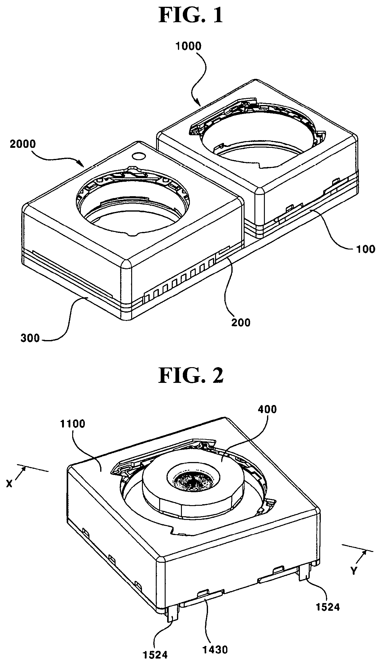
[0037]FIG. 1 is a perspective view of a dual camera module according to the present invention.

[0038]FIG. 2 is a perspective view of a first lens driving device according to the first embodiment of the present invention in which the lens module is coupled.

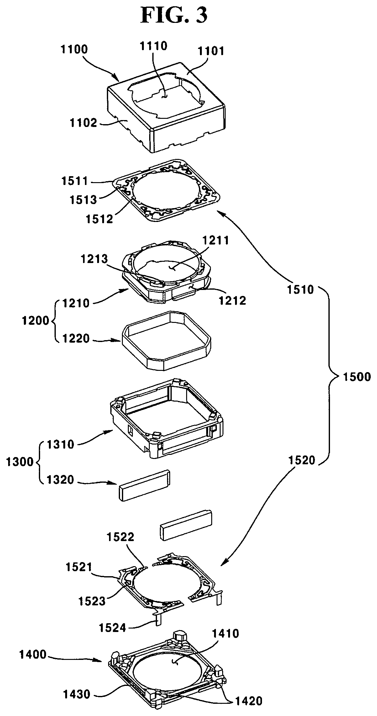
[0039]FIG. 3 is an exploded perspective view of the first lens driving device according to the first embodiment of the present invention.

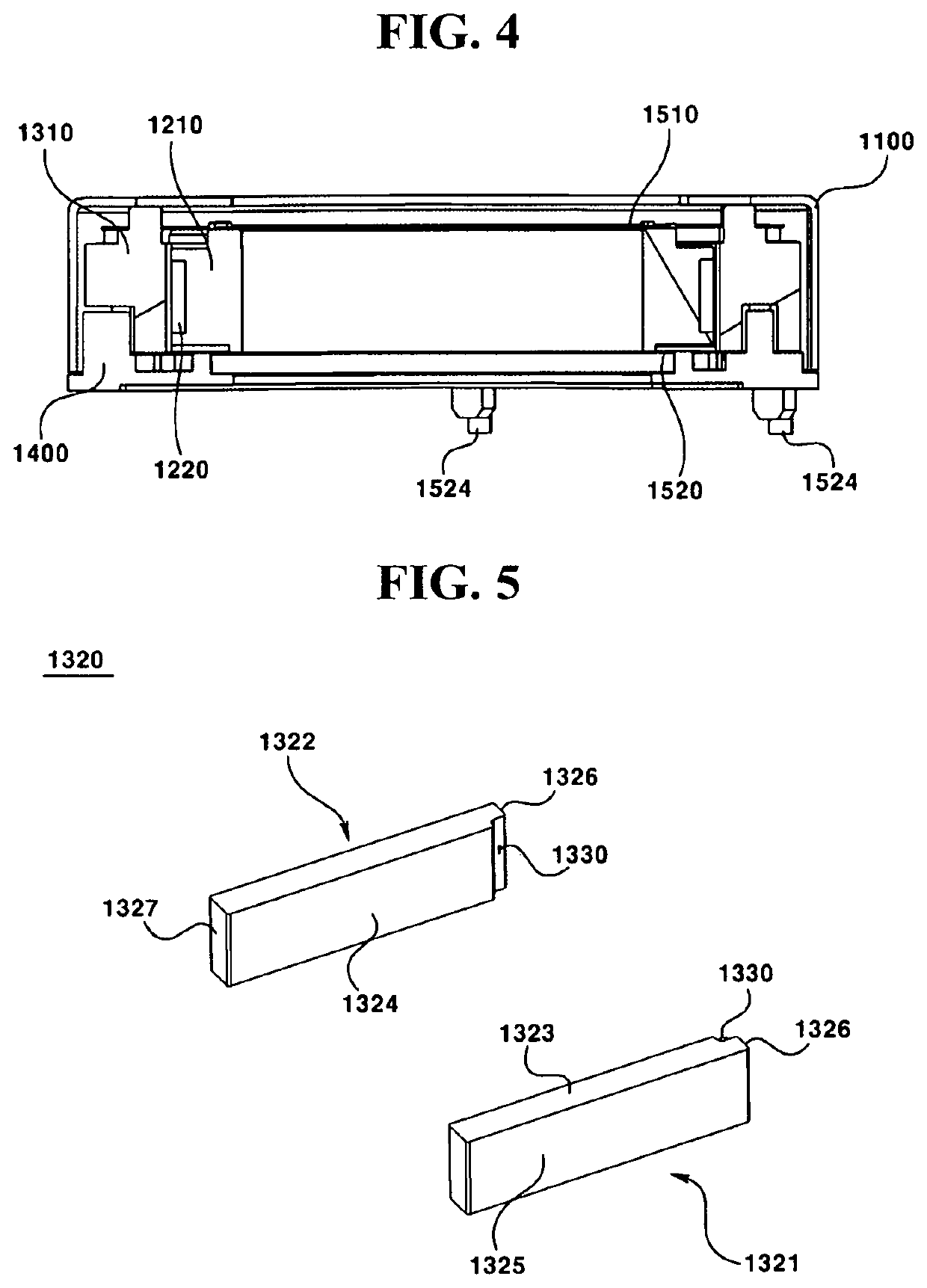
[0040]FIG. 4 is a cross-sectional view taken along the line X-Y in FIG. 2.

[0041]FIG. 5 is a perspective view showing a magnet of the first lens driving device according to the first embodiment of the present invention.

[0042]FIG. 6 is a conceptual view showing a magnet of the first lens driving device and a magnet of the second lens driving device according to the first embodiment of the present invention.

[0043]FIG. 7 is a perspective view showing a housing of the first lens driving device according to the first embodiment of the present invention.

[0044]FIG. 8 is a side view showing the housing of t...

second embodiment

[0051]FIG. 15 is a perspective view of a lens module coupled to a first lens driving device according to the present invention.

[0052]FIG. 16 is an exploded perspective view of the first lens driving device according to the second embodiment of the present invention.

[0053]FIG. 17 is a sectional view taken along the line X-Y in FIG. 15.

[0054]FIG. 18 is a perspective view showing a magnet of the first lens driving device according to the second embodiment of the present invention.

[0055]FIG. 19 is a conceptual view showing a magnet of the first lens driving device and a magnet of the second lens driving device according to the second embodiment of the present invention.

[0056]FIG. 20 is a conceptual diagram showing a magnet and related structures of the first lens driving device according to the second embodiment of the present invention.

[0057]FIG. 21 is a perspective view showing the housing of the first lens driving device according to the second embodiment of the present invention.

[00...

third embodiment

[0066]FIG. 30 is a perspective view of a lens driving device according to the present invention.

[0067]FIG. 31 is a sectional view taken along the line X-Y in FIG. 30.

[0068]FIG. 32 is an exploded perspective view of a lens driving device according to the third embodiment of the present invention.

[0069]FIG. 33 is an exploded perspective view of the lens driving device according to the third embodiment of the present invention, viewed from a direction different from that of FIG. 32.

[0070]FIG. 34 is an exploded perspective view showing a first mover and related structures according to the third embodiment of the present invention.

[0071]FIG. 35 is an exploded perspective view showing a second mover according to the third embodiment of the present invention.

[0072]FIG. 36 is an exploded perspective view showing a stator according to the third embodiment of the present invention.

[0073]FIG. 37 is an exploded perspective view showing an elastic member, a support member, and related structures...


PUM


Abstract

A camera module comprises: a first camera module; and a second camera module including a second side that faces a first side of the first camera module, wherein the first camera module comprises: a housing; a bobbin disposed inside the housing; a coil disposed on the outer circumferential surface of the bobbin; and two magnets, facing each other, that are arranged at the sides of the housing in the direction perpendicular to the first side of the first camera module, so as to face the coil, wherein each of the two magnets comprises: an upper surface; a lower surface; an inner surface facing the coil; an outer surface disposed on the reverse side to the inner surface; and two side surfaces connecting the inner surface and the outer surface, wherein a depressed part is provided on the side surface of the magnet, among the two side surfaces of the magnet, that is disposed on the first side of the first camera module, the depressed part being formed by recessing a portion of the side surface of the magnet, and the area of the inner surface of the magnet is smaller than the area of the outer surface of the magnet.

Description

CROSS REFERENCE TO RELATED APPLICATIONS[0001]This application is the National Phase of PCT International Application No. PCT / KR2018 / 001814, filed on Feb. 12, 2018, which claims priority under 35 U.S.C. 119(a) to Patent Application Nos. 10-2017-0018826, filed in the Republic of Korea on Feb. 10, 2017; 10-2017-0027847, filed in the Republic of Korea on Mar. 3, 2017, and 10-2017-0045169, filed in the Republic of Korea on Apr. 7, 2017, all of which are hereby expressly incorporated by reference into the present application.TECHNICAL FIELD[0002]The present invention relates to a lens driving device, a camera module and an optical instrument.BACKGROUND ART[0003]The following description merely provides background information for the present embodiment and does not describe the prior art.[0004]With the widespread use of various portable terminals and the commercialization of wireless Internet services, demands of consumers related to portable terminals have diversified, and various kinds o...

Claims


Application Information

Patent Timeline
Patent Type & Authority Patents(United States)
IPC IPC(8): G03B13/36G02B7/09G02B27/64G03B5/00H04N5/225
CPCG03B13/36G02B7/09G02B27/646G03B5/00H04N5/2252H04N5/2253H04N5/2254H04N5/2257G03B2205/0007G03B2205/0069G03B5/02G03B17/14G03B19/07G03B3/10G03B30/00G03B2205/00H04N23/54H04N23/45H04N23/57H04N23/51H04N23/55
Inventor LEE, SUNG GUKLEE, SEONG MINMIN, SANG JUNJUNG, TAE JIN
Owner LG INNOTEK CO LTD
Why Eureka
Try Eureka