High efficiency counterbalanced dual axis solar tracking array frame system

a solar tracking array and dual-axis technology, applied in the field of solar tracking array frames, can solve the problems of reducing the efficiency of solar energy capture, reducing the efficiency of solar energy production, and capturing the maximum solar power, so as to reduce the force acting directly on the panels, reduce the wind load, and reduce the effect of wind load

Active Publication Date: 2011-03-31
SCANLON MARK +1
View PDF27 Cites 105 Cited by
  • Summary
  • Abstract
  • Description
  • Claims
  • Application Information

AI Technical Summary

Benefits of technology

[0016]The system minimizes wind loading in multiple ways. The separation between panels results in spaces or holes through which wind passes unrestricted. Therefore the array does not form a large surface upon which the wind can act. These holes also create turbulence as the wind pass through them, lessening the wind's power on any other arrays in the wind's path. In addition, based on a command sent either manually, e.g. via a switch, or from a controller based on wind direction and/or speed data from sensors, the panels may be rotated into a vertical position so that in the best case the wind passes between the panels (louvering) exerting almost no force, in the average case, the wind strikes the panels a

Problems solved by technology

A fundamental challenge in the solar energy industry is to efficiently absorb and convert solar radiation into usable forms of energy.
In general, static systems are far from optimized because they do not follow the sun and therefore do not capture the maximum solar power.
Further, even where static PV panels are installed at the best possible solar angle, on average, they only produce 40-60% of the power that they are capable of producing.
In these systems, the number of panels that may be mounted is limited by the size and strength of the central pole

Method used


Image

  • High efficiency counterbalanced dual axis solar tracking array frame system
  • High efficiency counterbalanced dual axis solar tracking array frame system
  • High efficiency counterbalanced dual axis solar tracking array frame system

Examples


Embodiment Construction

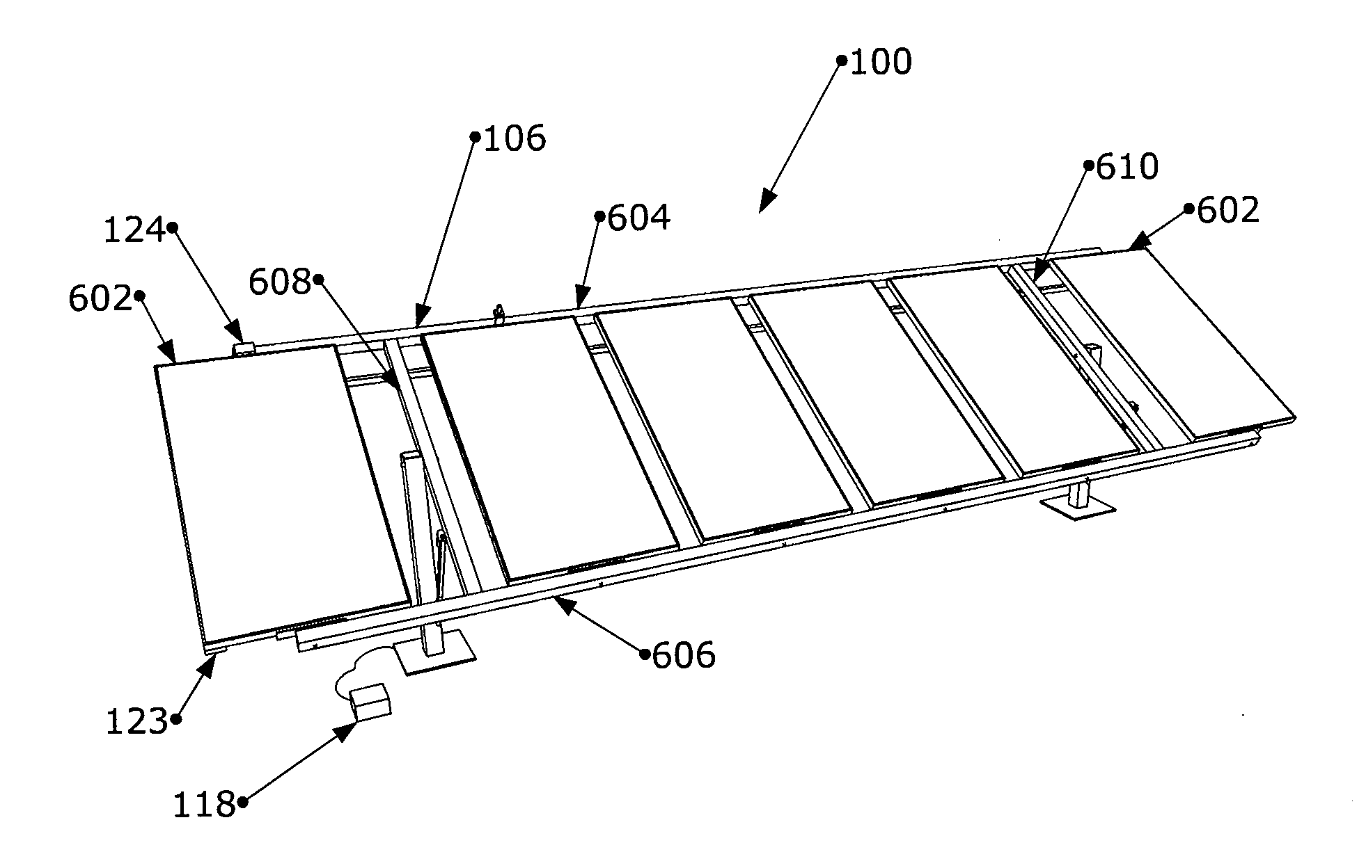
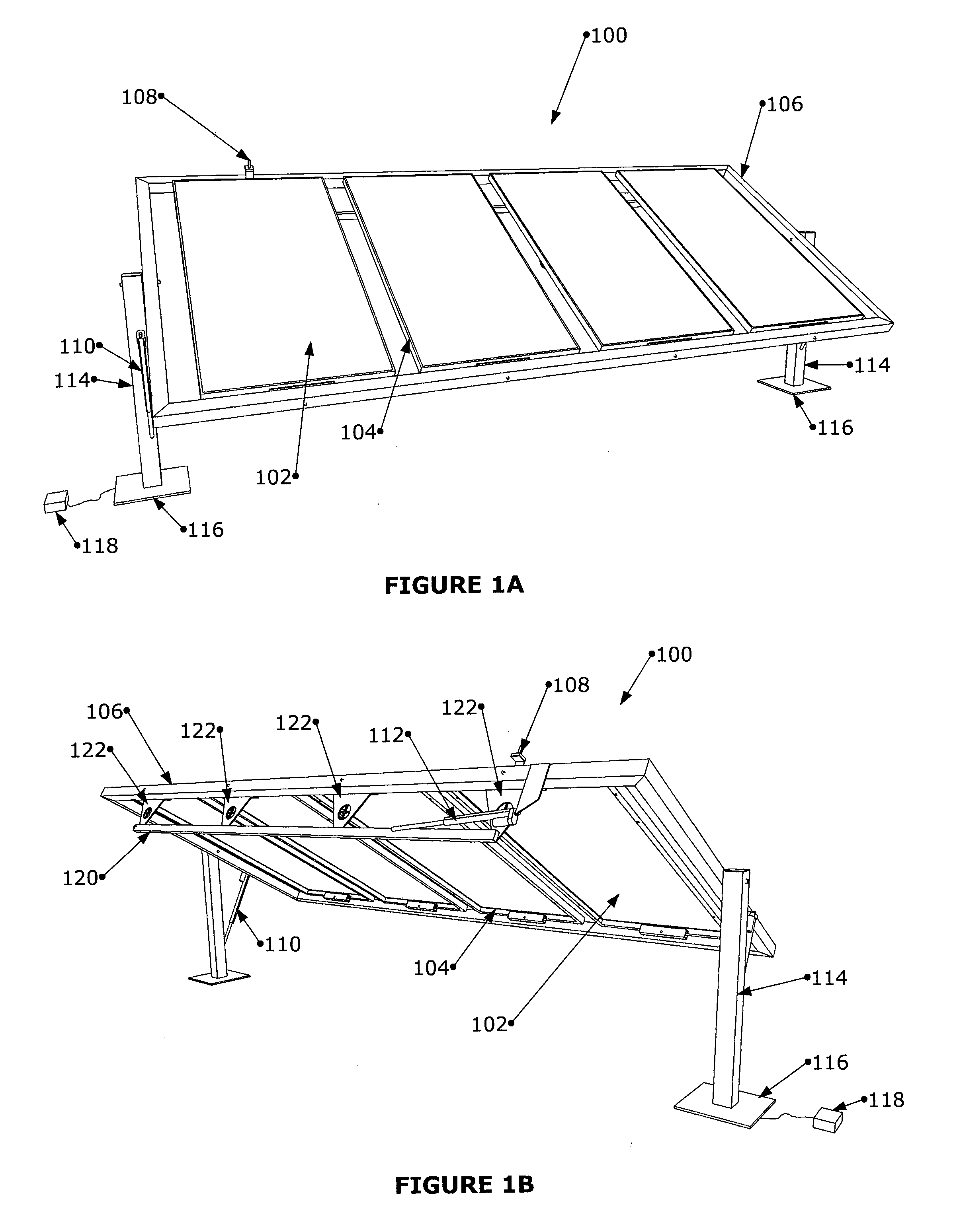
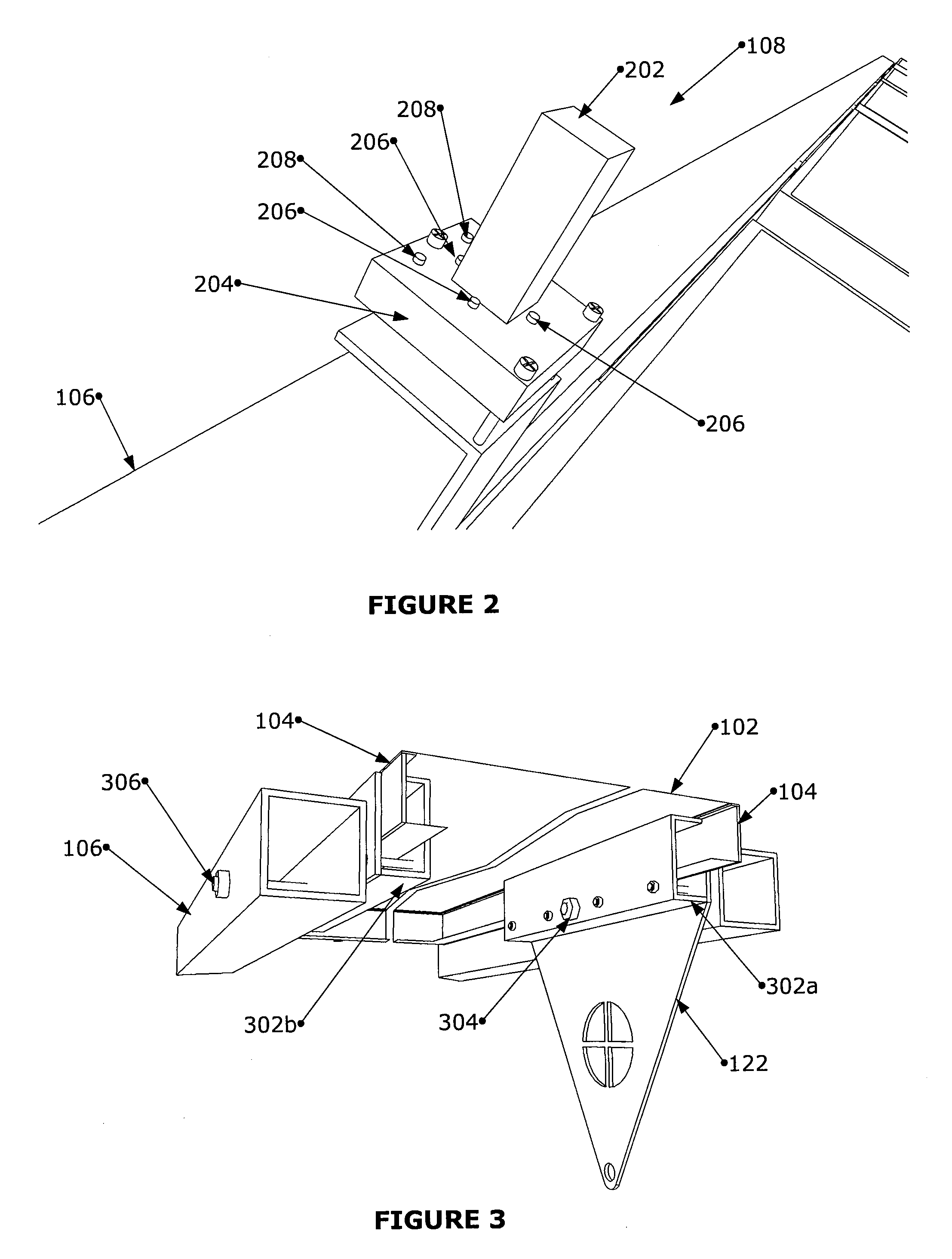
[0036]The detailed description of exemplary embodiments herein makes reference to the accompanying Figures, which show the exemplary embodiments by way of illustration and its best mode. While these exemplary embodiments are described in sufficient detail to enable those skilled in the art to practice the invention, it should be understood that other embodiments may be realized and that logical and mechanical changes may be made without departing from the spirit and scope of the invention. Thus, the detailed description herein is presented for purposes of illustration only and not of limitation. For example, the steps recited in any of the method or process descriptions may be executed in any order and are not limited to the order presented. Moreover, any of the functions or steps may be outsourced to or performed by one or more third parties. Furthermore, any reference to singular includes plural embodiments, and any reference to more than one component may include a singular embod...


PUM


Abstract

A high efficiency, environmentally friendly system comprising a plurality of photovoltaic solar collecting panels (PV panels) is disclosed. The system comprises an outer frame to which a plurality of inner frames are mounted to which the plurality of PV panels are attached. To minimize shadowing by the outer frame upon one or more PV panels, at least one PV panel may extend beyond an endpoint of the main frame. The system also comprises an outer frame rotation actuator that rotates the outer frame and an inner frame rotation actuator that rotates the inner frames and the plurality of PV panels. The solar tracking array frames disclosed herein help to improve the quality of the environment by conserving a variety of energy resources (e.g., fossil fuels, hydroelectric energy, etc.) The solar tracking array frames disclosed herein also help to reduce greenhouse gas emissions, as solar tracking array frames do not produce carbon dioxide byproducts.

Description

CROSS-REFERENCE TO RELATED APPLICATIONS[0001]This application claims the benefit of U.S. Provisional Patent Application Ser. No. 61 / 318,577, entitled COUNTERBALANCED DUAL AXIS SOLAR TRACKING ARRAY FRAME, filed Mar. 29, 2010, which is incorporated by reference herein in its entirety.FIELD OF INVENTION[0002]The present disclosure relates to solar tracking array frames. The solar tracking array frames disclosed herein improve the quality of the environment by conserving a variety of energy resources (e.g., fossil fuels, hydroelectric energy, etc.) The solar tracking array frames disclosed herein also reduce greenhouse gas emissions, as solar tracking array frames do not produce carbon dioxide byproducts.BACKGROUND OF THE INVENTION[0003]A fundamental challenge in the solar energy industry is to efficiently absorb and convert solar radiation into usable forms of energy. To this end, a variety of modern photovoltaic solar collecting (“PV”) systems exist. For example, some PV systems are s...

Claims


Application Information

Patent Timeline
IPC IPC(8): H01L31/052F24S50/20
CPCF24J2/38F24J2/5254F24J2/5258F24J2/5424F24J2002/5468H02S20/00Y02E10/50F24J2002/0084F24J2/523F24J2/5232Y02E10/47H02S20/32H02S10/40H02S20/10H02S20/22Y02B10/10F24S30/455F24S25/632F24S2020/16F24S50/20F24S25/10F24S25/12F24S25/636F24S2030/136E04H6/025E04H6/10
Inventor SCANLON, MARK
Owner SCANLON MARK
Why Eureka
Try Eureka