Three-body joining using friction stir processing techniques

a technology of friction stir and processing technique, applied in the direction of soldering apparatus, manufacturing tools,auxillary welding devices, etc., can solve the problems of limiting load carrying capacity, inability to use screws or bolts, and high cost of multiple components and assemblies

Active Publication Date: 2011-03-31
MAZAK CORP
View PDF8 Cites 19 Cited by
  • Summary
  • Abstract
  • Description
  • Claims
  • Application Information

AI Technical Summary

Benefits of technology

[0021]In a first aspect of the invention, a friction stir tool is provided to perform friction stir riveting using a at least a partially consumable pin, wherein the pin includes a cutting edge on a bottom surface thereof, wherein the tool is rotated at a first speed to enable cutting by the pin into a first material that is overlapping a second material, wherein after the pin has cut to a sufficient depth, the rotational speed of the tool is increased to thereby enable plasticization of the consumable pin, the first material, and the second material, wherein the tool is then rapidly decelerated until stopped, enabling diffusion bonding between the pin, the first material and the second material.

Problems solved by technology

Many applications cannot use screws or bolts because the threads have limiting load carrying capability, the high cost of multiple components and assembly, the cost of the hole that must be placed in the work pieces and / or the space required for the fasteners.
Rivets have perhaps the greatest joining strength per unit area and volume of any mechanical fastener but the mechanical deformation of the rivet head reduces the energy absorbing capability as well as elongation.
High melting temperature materials (HMTM) such as steel, stainless steel and nickel base alloys can be welded but the joint strength is limited to problems associated with fusion welding.
These problems include, but are not limited to, solidification defects, hard / soft zones within the weld macrostructure, residual stresses resulting from liquid to solid phase transformation, porosity, cracking, non-uniform and unpredictable microstructures, corrosion susceptibility, work piece deformation, and loss of work piece base material properties.
Post weld operations are often needed to repair distortion or evaluate the weld nondestructively and add cost to the process.
In addition, there are health issues related to hexavalent chromium and manganese exposure as well as potential retina damage to the operator if proper safety procedures are not followed.
Advanced high strength steels (Dual Phase and TRIP steels) could be used in the frame construction to dramatically lower vehicle weight but these materials have not been used because of fusion weldability issues.
Some of these materials are non-fusion weldable, or just difficult to weld at all.
The main disadvantage with FSW is a remaining hole left in the work pieces at the end of the weld.
A retractable pin can be used as the weld progresses to eliminate the end hole; however the tool and equipment requirements are extensive and costly.
Tool geometries that allow the tool to be extracted from the weld gradually during FSW can also be used but the added process time combined with the added heat cycle over an existing weld increases cost and decreases base metal properties.
The disadvantage with this method is the hole 26 left behind from the pin as shown in FIG. 2.
This method is quite cumbersome because of the large spindle head, fixturing requirements, and loads needed to make a spot weld.

Method used


Image

  • Three-body joining using friction stir processing techniques
  • Three-body joining using friction stir processing techniques
  • Three-body joining using friction stir processing techniques

Examples


Embodiment Construction

[0029]Reference will now be made to the drawings in which the various elements of the present invention will be given numerical designations and in which the invention will be discussed so as to enable one skilled in the art to make and use the invention. It is to be understood that the following description is only exemplary of the principles of the present invention, and should not be viewed as narrowing the claims which follow.

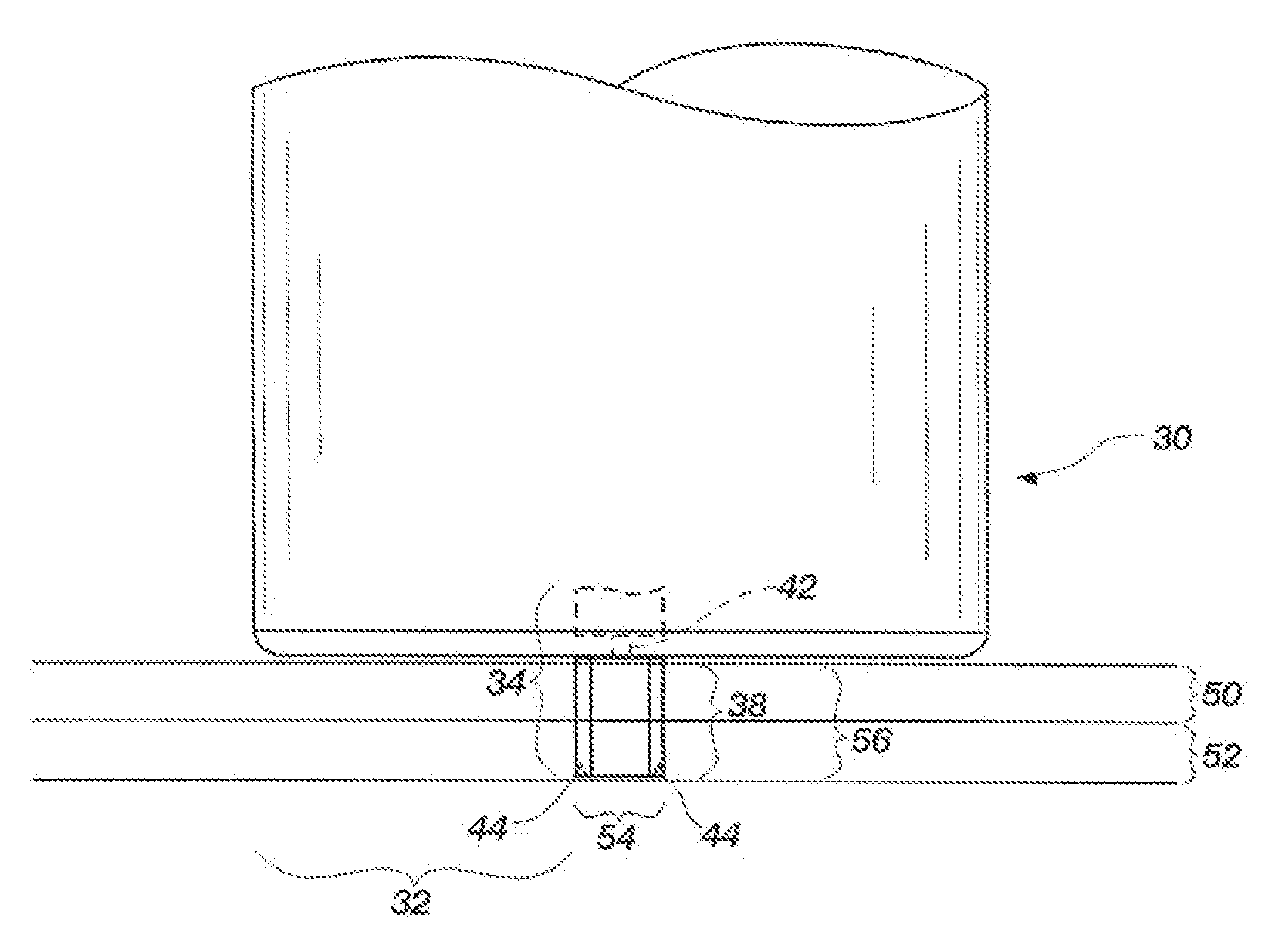
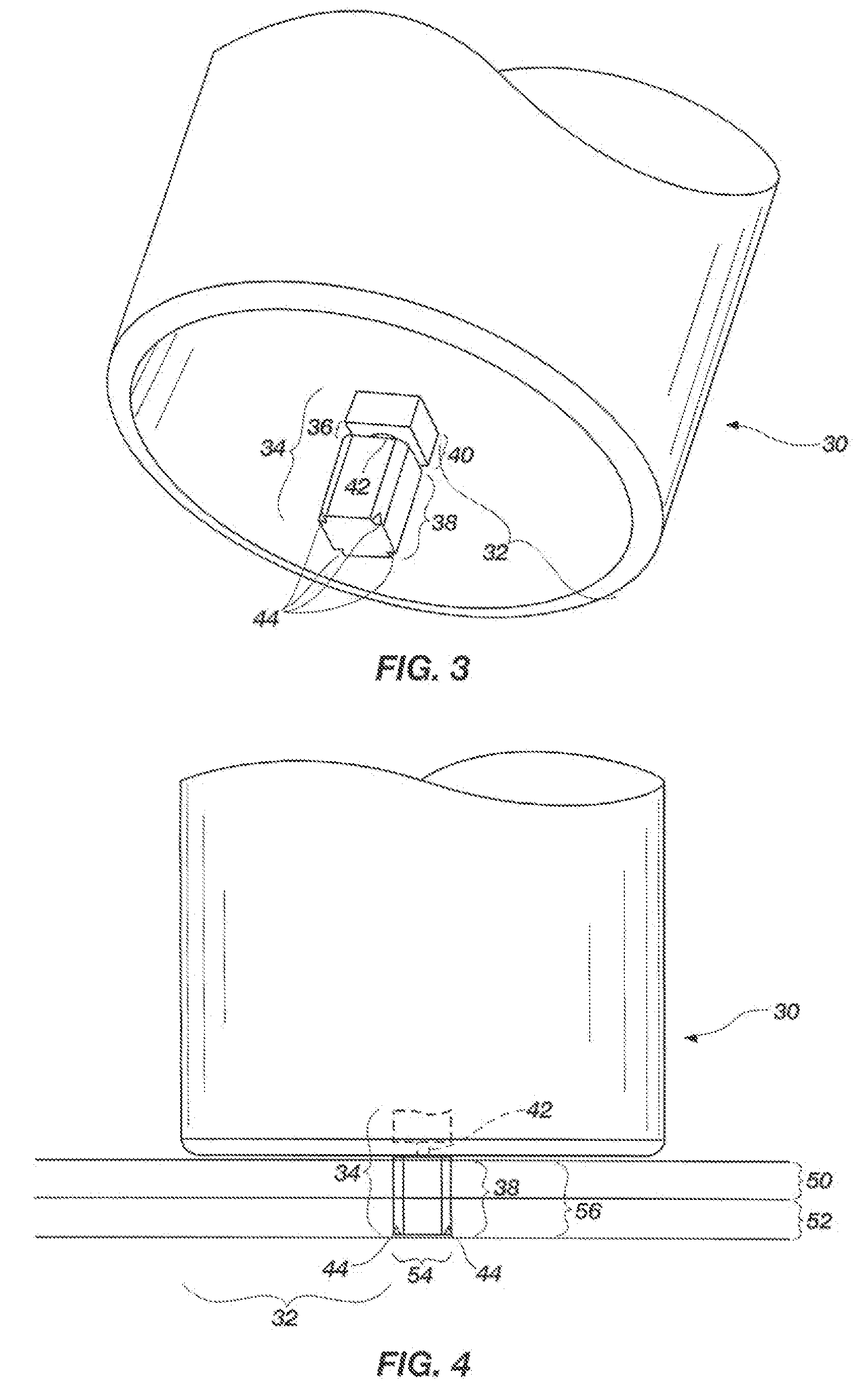
[0030]In a first aspect of the invention, a novel approach is used to solve many of the joining problems mentioned above. A rotating friction stir riveting tool having a non-consumable shoulder combined with a detachable and at least partially consumable pin forms the basis of a friction stir riveting joining method of the present invention. The pin may be totally consumable or partially consumable. FIG. 3 shows an example of how the tool can be constructed.

[0031]FIG. 3 shows a friction stir riveting tool 30 having a shoulder area 32 and a detachable and at...


PUM

PropertyMeasurementUnit
Travel speedsaaaaaaaaaa
diameteraaaaaaaaaa
speedaaaaaaaaaa

Abstract

A friction stir tool is provided to perform friction stir riveting using a partially consumable pin, wherein the pin includes a cutting edge on a bottom surface thereof, wherein the tool is rotated at a first speed to enable cutting by the pin into a first material that is overlapping a second material, wherein after the pin has cut to a sufficient depth, the rotational speed of the tool is increased to thereby enable plasticization of the consumable pin, the first material, and the second material, wherein the tool is then rapidly decelerated until stopped, enabling diffusion bonding between the pin, the first material and the second material.

Description

RELATED APPLICATIONS[0001]This application claims priority to and incorporates by reference all of the subject matter of U.S. Patent Application Ser. No. 60 / 804,628, filed Jun. 13, 2006, and of U.S. Patent Application Ser. No. 60 / 816,396, filed Jun. 23, 2006.BACKGROUND OF THE INVENTION[0002]1. Field of the Invention[0003]This invention relates generally to friction stir joining methods. More specifically, the present invention is a method of joining metal work pieces together using a consumable friction stir tool that has at least a partially consumable pin, wherein the pin has a cutting edge that cuts through a first work piece material when rotated at a first speed. After at least cutting through the first work piece material to a sufficient depth, the rotational speed of the tool is changed to cause plasticization of the pin itself, as well as the first and second work piece materials being joined. After sufficient heating of the first and second work piece materials and the pin,...

Claims


Application Information

Patent Timeline
Patent Type & Authority Applications(United States)
IPC IPC(8): B23K20/12
CPCB23K20/123B23K20/128B23K20/127B23K20/1255
Inventor PACKER, SCOTT M.STEEL, RUSSELL J.BABB, JONATHAN A.MILES, MICHAEL P.KOHKONEN, KENT
Owner MAZAK CORP
Why Eureka
Try Eureka