

Disc discrimination apparatus and method
- Summary
- Abstract
- Description
- Claims
- Application Information
AI Technical Summary
Benefits of technology
Problems solved by technology
Method used
Image


Examples
Embodiment Construction
[0030]FIG. 1 shows an apparatus 10 for reproducing recorded information from an optical disc according to a first embodiment of this invention. The apparatus 10 may include an optical-disc player such as a CD (Compact Disc) player. The optical-disc player 10 may be provided in an automotive vehicle. The optical-disc player 10 is divided into an optical-disc drive and other portions.
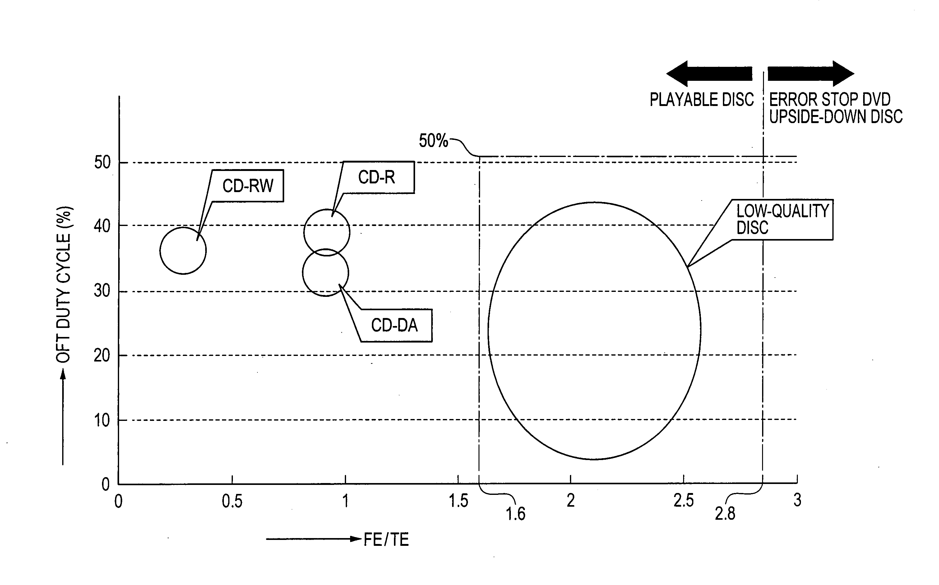
[0031]The optical-disc player 10 can drive or play an optical disc 11 such as a CD being one of a CD-DA, a CD-R, and a CD-RW. The CD-R is a standard-quality CD-R or a low-quality CD-R. The low-quality CD-R has a quality lower than a standard quality. A first example of the low-quality CD-R has a track pitch narrower than a standard value. A second example of the low-quality CD-R has optical characteristics causing a small tracking error amplitude or a great crosstalk.
[0032]When being chucked in the optical-disc player 10, the optical disc 11 is on a turntable (not shown) and is pressed thereto from above ...
PUM
 Abstract
Description
Claims
Application Information